Range Rover Classic. Manual - part 103


  Index      Land Rover     Range Rover Classic - service manual 1995 year


Search            


Content   ..  101  102  103  104   ..


Range Rover Classic. Manual - part 103


57

STEERING

6

REPAIR

Refit

6. Position reservoir, connect feed and return

hoses and tighten clamps to

3 Nm.

7. Fit reservoir in clamp, tighten clamp bolt.
8. Fill reservoir to ’MAX’ mark on dipstick with

power steering fluid.

See LUBRICANTS,

FLUIDS AND CAPACITIES, Information,
Recommended Lubricants and Fluids

9. Fit undertray.

10. Bleed power steering system.

See Power

Steering System - Bleed

POWER STEERING PUMP DRIVE BELT

Service repair no - 57.20.02

NOTE: For details of drive belt remove and
refit.

See ENGINE, Repair, Drive Belt

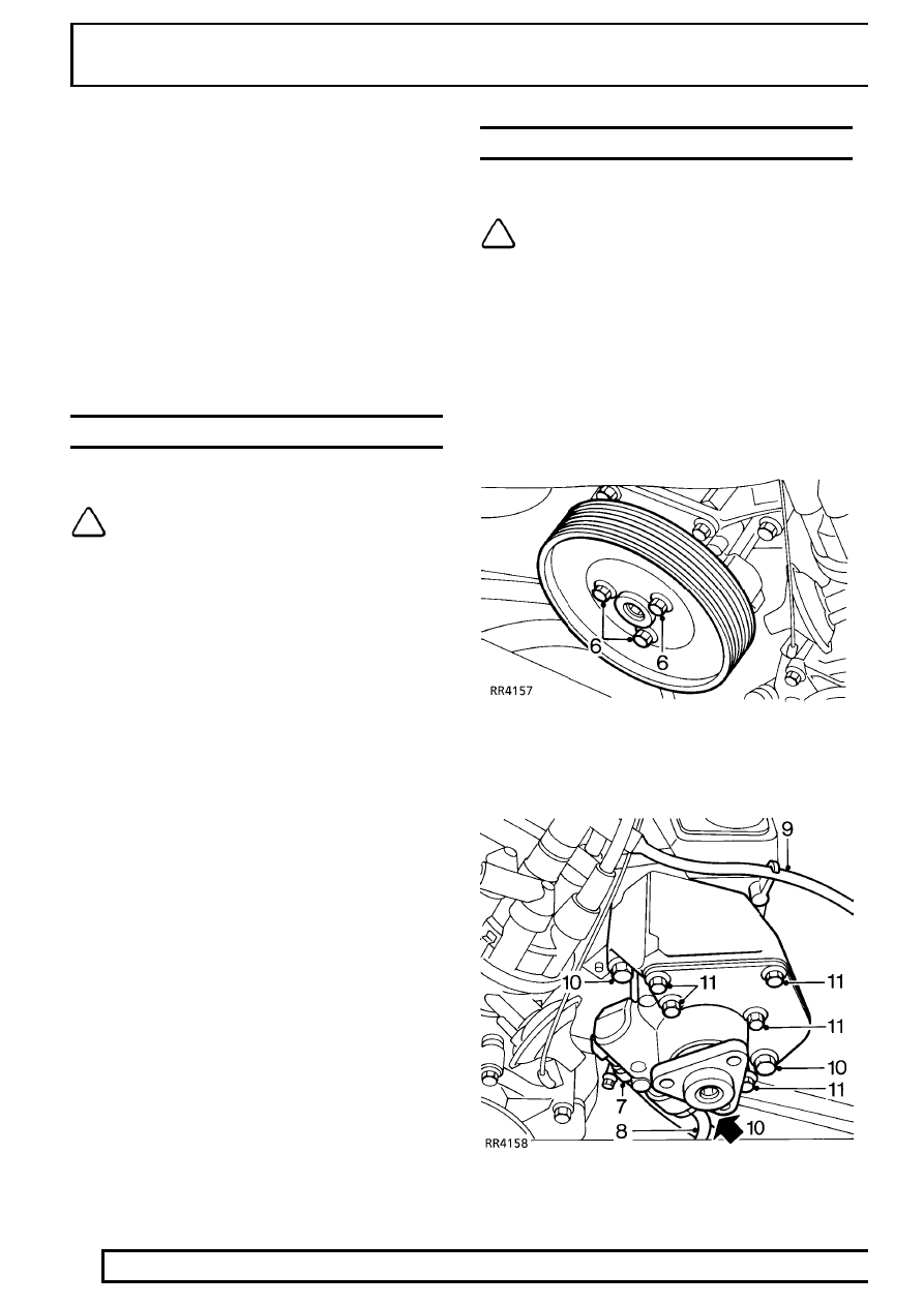
POWER STEERING PUMP - V8i

Service repair no - 57.20.14

NOTE: The power steering pump is not
serviceable. Fit new pump if worn or
damaged.

Remove

1. Disconnect battery negative lead.
2. Remove drive belt from steering pump.

See

ENGINE, Repair, Drive Belt

3. Remove undertray.
4. Remove fan blades and viscous coupling.

See

COOLING SYSTEM, Repair, Viscous
Coupling, Fan Blades, Pulley and Fan Cowl

5. Position drain tin beneath steering pump.

6. Using a 9 mm Allen key to restrain steering

pump pulley, remove 3 bolts securing pulley to
pump; remove pulley.

STEERING

7

REPAIR

7. Loosen clamp securing reservoir hose to

steering pump; disconnect hose.

8. Disconnect high pressure pipe from steering

pump.

CAUTION: Plug the connections.

9. Release ht lead from clip

10. Remove 3 bolts securing steering pump.

Remove pump and recover engine lifting
bracket.

NOTE:

Do not carry out further

dismantling if component is removed for
access only.

11. Remove 5 bolts securing front mounting plate.
12. Fit front mounting plate to replacement steering

pump. Tighten bolts to

9 Nm.

Refit

13. Position steering pump and engine lifting plate,

fit bolts. Tighten to

35 Nm. Secure ht lead in

clip.

14. Connect high pressure pipe to steering pump,

tighten union to

20 Nm.

15. Connect reservoir hose to steering pump.

Tighten clamp to

3 Nm.

16. Position pulley to pump, coat threads of bolts

with Loctite 242.

17. Restrain pulley using a 9 mm Allen key, fit bolts.

Tighten to

10 Nm.

18. Fit drive belt.

See ENGINE, Repair, Drive Belt

19. Fit fan blades and viscous coupling.

See

COOLING SYSTEM, Repair, Viscous
Coupling, Fan Blades, Pulley and Fan Cowl

20. Fit undertray.
21. Reconnect battery negative lead.
22. Bleed power steering system.

See Power

Steering System - Bleed

POWER STEERING PUMP - Tdi

Service repair no - 57.20.14

Remove

1. Remove fan blades and viscous coupling.

See

COOLING SYSTEM, Repair, Viscous
Coupling, Fan Blades, Pulley and Fan Cowl

2. Restrain steering pump pulley, loosen but do not

remove 3 bolts securing pulley.

3. Remove drive belt.

See ENGINE, Repair,

Drive Belt

4. Remove 3 bolts securing steering pump pulley,

remove pulley.

5. Remove undertray.
6. Position drain tin beneath steering pump.

57

STEERING

8

REPAIR

7. Loosen clamp securing reservoir hose to

steering pump, disconnect hose.

8. Disconnect high pressure pipe from steering

pump.

CAUTION: Plug the connections.

9. Remove 4 bolts securing steering pump to

mounting bracket, remove pump.

NOTE:

Do not carry out further

dismantling if component is removed for
access only.

10. Remove 3 bolts securing mounting plate to

pump, remove plate.

11. Fit mounting plate to replacement steering

pump. Tighten bolts to

9 Nm.

Refit

12. Position steering pump, fit 3 bolts. Tighten to

35

Nm.

13. Connect high pressure pipe to steering pump.

Tighten to

20 Nm.

14. Connect reservoir hose to steering pump.

Tighten clamp to

3 Nm.

15. Position pulley to steering pump, coat threads of

bolts with Loctite 242; fit but do not fully tighten 3
bolts.

16. Fit drive belt.

See ENGINE, Repair, Drive Belt.

17. Restrain steering pump pulley, tighten bolts to

10

Nm.

18. Fit fan blades and viscous coupling.

See

COOLING SYSTEM, Repair, Viscous
Coupling, Fan Blades, Pulley and Fan Cowl.

19. Fit undertray.
20. Bleed power steering system.

See Power

Steering System - Bleed.

STEERING

9

REPAIR

LOWER STEERING SHAFT AND UNIVERSAL
JOINTS

Service repair no - 57.40.25

CAUTION: Before removing any parts of
steering linkage, it is imperative that road
wheels are positioned straight ahead.

Then steering wheel removed to prevent rotary
coupler being wound up or damaged.

CAUTION: After refitting steering linkage
parts follow correct procedure to ensure
that road wheels, steering box and

steering wheel are correctly positioned relative to
each other when in straight ahead condition. If
steering wheel requires repositioning, ensure that
drive pegs on rotary coupler are correctly
positioned before steering wheel is replaced.

This ensures drive pegs locate in their holes in
rear of steering wheel.

After final alignment connect rotary coupler,
tighten steering wheel securing nut and fit air bag
module - if fitted or steering wheel trim pad.

Remove

1. Ensure road wheels are straight ahead.
2. Remove pinch bolt securing top universal joint to

steering column.

3. Remove 2 pinch bolts securing lower universal

joint.

4. Move lower shaft up to release lower universal

joint from steering box splines. Remove lower
shaft.

5. Remove universal joint from lower shaft.

NOTE: Do not dismantle upper coupling
joint. Steering shaft, rubber coupling and
top universal joint is only available as an

assembly.

6. Inspect lower universal joint for wear and

excessive play, renew if necessary.

7. Inspect top universal joint and rubber coupling,

renew lower shaft as an assembly if necessary.

8. Inspect universal joints for stiffness, lubricate if

necessary.

NOTE: Prior to fitting a replacement
steering shaft check the following:

9. Release stud fasteners securing heat shield (if

fitted).

10. Check that indicator clip coloured red is fully

inserted under head of compression joint bolt.

WARNING: If clip is displaced, no attempt
must be made to drive clip into
engagement, a new shaft assembly must

be fitted.

11. Secure heat shield stud fasteners (if fitted).

Refit

NOTE: Fit universal joints so pinch bolt
holes line up with flat on shaft.

12. Position lower universal joint on shaft.
13. Position shaft assembly onto steering column.

Move assembly up spline to enable lower
universal joint to fit onto steering box splines.

14. Align bolt holes with grooves in splines. Fit pinch

bolts. Tighten to

25 Nm.


Content   ..  101  102  103  104   ..