Range Rover Classic. Manual - part 85


  Index      Land Rover     Range Rover Classic - service manual 1995 year


Search            


Content   ..  83  84  85  86   ..


Range Rover Classic. Manual - part 85


51

REAR AXLE AND FINAL DRIVE

2

REPAIR

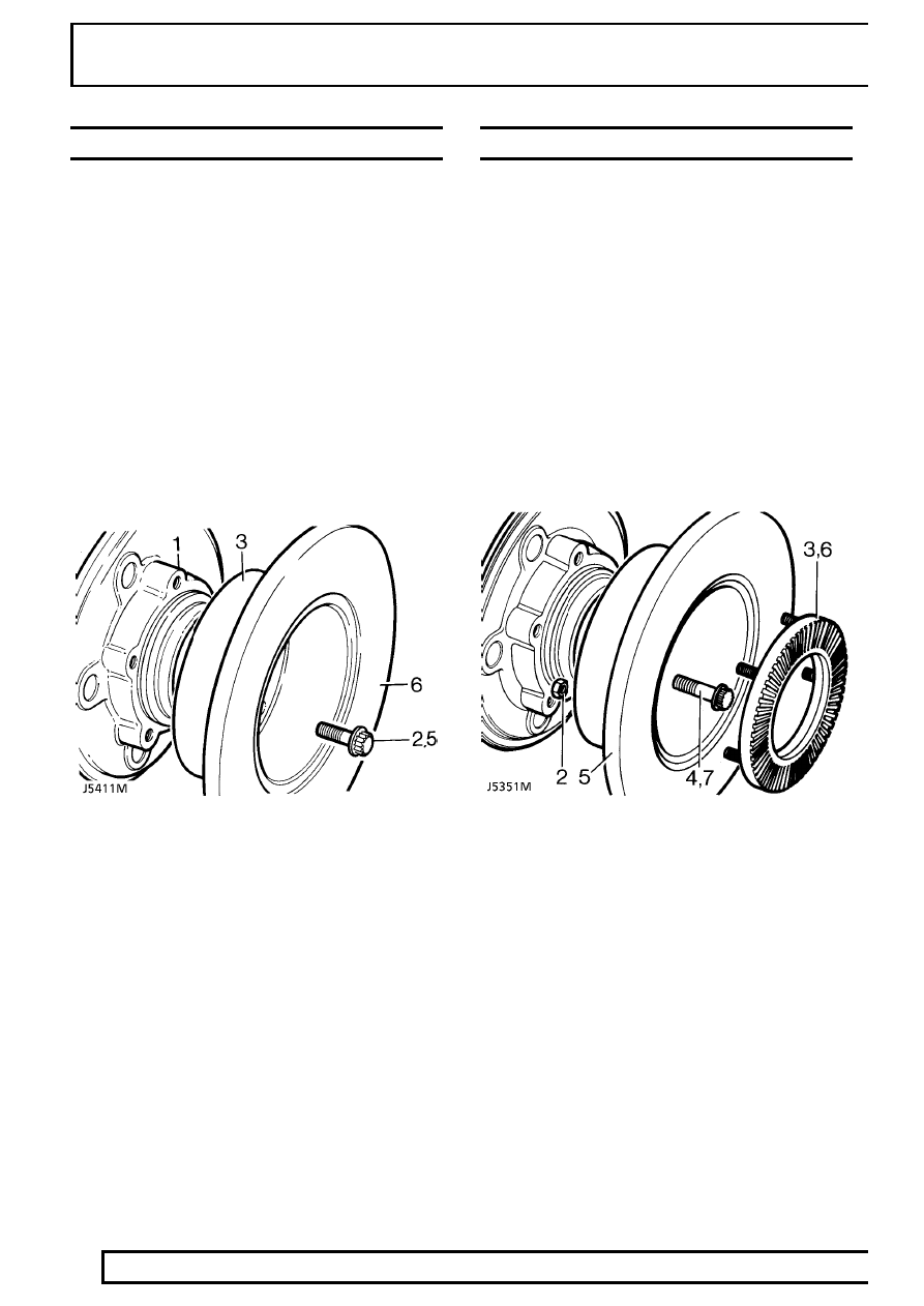
REAR BRAKE DISC NON ABS

Service repair no - 70.10.11.

Remove

1. Remove rear hub assembly.

See Rear Hub

Assembly

2. Remove disc bolts.
3. Remove disc from rear hub.

Refit

4. Fit disc to rear hub.
5. Fit disc bolts. Tighten to

73 Nm.

6. Check total disc run out, this must not exceed

0,15 mm. If necessary reposition disc.

7. Fit rear hub assembly.

See Rear Hub

Assembly

Disc reclamation

8. Check disc thickness. This dimension may be

reduced to minimum thickness of 12 mm.
Machine equal amounts off each face.

REAR BRAKE DISCS ABS

Service repair no - 70.11.11.

Remove

1. Remove rear hub assembly.

See Rear Hub

Assembly

2. Remove five nyloc nuts.
3. Remove sensor ring.
4. Remove five hub to disc retaining bolts.
5. Remove disc from hub.

Refit

6. Fit disc onto hub.
7. Apply loctite 270 and fit hub to disc retaining

bolts. Tighten to

73 Nm.

8. Using new nyloc nuts fit sensor ring.

9. Check total disc run out, this must not exceed

0,15 mm. If necessary reposition disc.

10. Fit hub assembly.

See Rear Hub Assembly

Disc reclamation

11. Check disc thickness. This dimension may be

reduced to a minimum thickness of 12 mm.
Machine equal amounts off each face.

REAR AXLE AND FINAL DRIVE

3

REPAIR

REAR HUB ASSEMBLY

Service repair no - 64.15.01

Remove

1. Place rear axle onto axle stands and remove

road wheel.

2. Release brake hose clips and remove brake

caliper bolts. Secure to one side.

WARNING: Take care not to kink brake
hose.

3. Remove five bolts and withdraw axle shaft.
4. Remove joint washer.
5. Bend back lock washer tabs.
6. Remove locknut and lock washer.
7. Remove hub adjusting nut.
8. Remove spacing washer.
9. Remove hub and brake disc assembly complete

with bearings.

REAR HUB COMPONENTS

1. Sensor ring retaining nut ABS.
2. Axle shaft.
3. Axle shaft joint washer.
4. Axle shaft retaining bolt (five off).
5. Lock nut.
6. Lock washer.
7. Hub adjusting nut.
8. Spacing washer.
9. Outer bearing.

10. Hub.
11. Inner bearing.
12. Grease seal.
13. Brake disc.
14. Disc retaining bolt (five off).
15. Sensor ring ABS.

51

REAR AXLE AND FINAL DRIVE

4

REPAIR

Refit

10. Clean stub axle. Retract ABS sensor slightly

from sensor sleeve, if applicable

11. Fit hub assembly to stub axle.
12. Fit spacing washer.
13. Fit hub adjusting nut. Tighten to

61 Nm.

Back off adjusting nut 90˚. Tighten to

4 Nm.

This will give the required hub end float of
0,010mm

14. Fit a new lock washer.

15. Fit locknut. Tighten to

61 Nm.

16. Tab over lock washer to secure adjusting nut

and locknut.

17. Using a new joint washer fit axle shaft to hub,

secure with five bolts. Tighten to

65 Nm.

18. Fit brake caliper. Tighten to

82 Nm.

Secure brake pipes to axle casing.

19. If applicable, set ABS brakes sensor.

Push sensor in until it touches sensor ring then
rotate hub to set sensor.

20. Fit road wheel, remove axle stands and final

tighten road wheel nuts to

126 Nm.

21. Operate footbrake to locate brake pads before

driving vehicle.

REAR AXLE AND FINAL DRIVE

1

OVERHAUL

AXLE DIFFERENTIAL ASSEMBLY

Service repair no - 51.15.07.

DISMANTLE

NOTE: Mark differential components so
their original positions relative to other
components is maintained. Bearing caps

must not be interchanged.

1. Remove axle shafts then differential assembly

fom axle.

2. Remove roll pin securing bearing nut locking

fingers to bearing caps. Remove locking fingers.

3. Loosen bearing cap bolts and mark caps for

assembly.

4. Using service tool LRT-54-508, remove bearing

adjusting nuts.

5. Remove bearing cap bolts and bearing caps.
6. Remove crown wheel differential unit and

bearings.

Remove pinion FRONT AXLE DIFFERENTIAL
ONLY

7. Remove pinion flange nut using service tool

LRT-51-003 to restrain flange.

8. Remove washer and pinion drive flange.

9. Remove pinion complete with bearing and outer

bearing shims.

10. Remove pinion flange oil seal, spacer and

bearing.

Remove pinion REAR AXLE DIFFERENTIAL ONLY

7. Remove pinion flange centralising peg using

service tool LRT 51-008.

8. Remove pinion flange nut using service tool

LRT-51-003 to restrain flange.

9. Remove pinion complete with bearing and outer

bearing shims.

10. Remove pinion flange oil seal, spacer and

bearing.

11. Using service tool LRT-54-505, remove pinion

head bearing track and shim and drive out outer
bearing of differential housing.


Content   ..  83  84  85  86   ..