Range Rover Classic. Manual - part 32


  Index      Land Rover     Range Rover Classic - service manual 1995 year


Search            


Content   ..  30  31  32  33   ..


Range Rover Classic. Manual - part 32


V8i

15

REPAIR

OIL SUMP

Service repair no - 12.60.44

Remove

1. Drain engine oil

See SECTION 10,

Maintenance, Under Vehicle Maintenance

2. Fit drain plug. Tighten to

40 Nm.

3. If fitted, disconnect low oil level sensor multiplug.

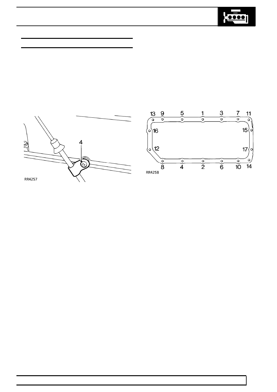
4. Remove bolt securing dipstick tube to rocker

cover.

5. Working form the centre outwards, progressively

loosen and remove 17 bolts securing sump.
Remove sump.

6. Remove all traces of sealant from mating

surfaces of sump, cylinder block and front cover,
using a suitable solvent or plastic scraper.

7. Degrease mating surfaces of sump, cylinder

block and front cover.

Refit

8. Apply RTV Hylosil White sealant to mating

surface of sump.

9. Position sump, tighten bolts finger tight.

10. Tighten bolts progressively in sequence shown.

Tighten to

18 Nm.

11. Fit bolt securing dipstick tube to rocker cover.
12. If fitted, connect low oil level sensor multiplug.

V8i

1

SPECIFICATIONS, TORQUE

TORQUE VALUES

NOTE: Torque wrenches should be regularly checked for accuracy to ensure that all fixings are
tightened to the correct torque.

Nm

Engine
Adaptor plate to crankshaft

84

........................................................................

Generator and power steering mounting bracket to cylinder head

30

............

Cylinder head:

Stage 1:

20

.............................................................................................

Stage 2: - Further 180˚ æ 5˚

Drive plate to converter

39

..............................................................................

Engine mountings to engine and chassis

55

..................................................

Engine mounting rubbers to brackets

30

........................................................

Flexible drive plate to crankshaft adaptor plate

41

..........................................

**

Flywheel to crankshaft bolts

78

.......................................................................

**

Lifting eye to cylinder heads

39

......................................................................

Main bearing cap rear bolts

92

.......................................................................

*

Oil sump drain plug

40

....................................................................................

Oil sump to cylinder block

18

..........................................................................

Rocker cover to cylinder head

9

....................................................................

Rocker shaft bracket to cylinder head

38

........................................................

Spark plug

21

..................................................................................................

Starter motor attachment

44

...........................................................................

* These bolts must have threads coated in lubricant EXP16A before assembly.

** These bolts must have threads coated in sealant Loctite 270

METRIC

Nm

M5

6

......................................................................................................

M6

9

......................................................................................................

M8

25

.....................................................................................................

M10

45

...................................................................................................

M12

90

...................................................................................................

M14

105

..................................................................................................

M16

180

..................................................................................................

UNC / UNF

1/4

9

......................................................................................................

5/16

24

...................................................................................................

3/8

39

.....................................................................................................

7/16

78

...................................................................................................

1/2

90

.....................................................................................................

5/8

136

....................................................................................................

NOTE: Torque values above are for all screws and bolts used except for those specified.

V8i

1

SERVICE TOOLS

ENGINE

LRT-12-034

Spring compressor

MS1519A

LRT-12-010

Crankshaft rear seal guide

RO1014

LRT-12-052

Oil pressure test kit

EMISSION CONTROL

1

DESCRIPTION AND OPERATION

EMISSION CONTROL

Three systems are used to control the vehicle
atmospheric emissions these are:

Engine crankcase fume emissions.
Fuel tank Evaporative emissions
Engine exhaust gas emissions.

Crankcase ventilation system

The crankcase ventilation system which is an integral
part of the air supply to the engine combustion
chambers, is often overlooked when diagnosing
problems associated with engine performance. A
blocked ventilation pipe or filter or excessive air leak
into the inlet system through a damaged pipe or
leaking gasket can effect the mixture, performance
and economy of the engine.

1. Three way connector
2. Air filter
3. Oil separator

The purpose of the crankcase ventilation system is to
ensure that any noxious gas generated in the engine
crankcase is rendered harmless by burning in the
combustion chambers as follows:
Oil laden noxious gas in the engine crankcase is
drawn through an oil separator 3 located on the right
cylinder head rocker cover, where the oil is separated
and returned to the sump. The gas flows through a
restrictor in the three way connection 1 and into the
inlet plenum chamber where it is drawn into the
combustion chambers and burned. The volume of
fresh air which is drawn from the atmospheric side of
the throttle butterfly to mix with the gas, depends on
the position of the throttle and the engine speed.

The air filter 2 fitted to the left cylinder head rocker
cover, must be maintained in clean condition to
ensure sufficient air enters the crankcase under
varying throttle openings and manifold depression, to
prevent excessive crankcase pressure or depression
developing.


Content   ..  30  31  32  33   ..