Range Rover 2. Electrical Manual - part 206


  Index      Land Rover     Range Rover 2 electrical troubleshooting manual (From Model 1997-1999 year)


Search            copyright infringement  


Content   ..  204  205  206  207   ..


Range Rover 2. Electrical Manual - part 206


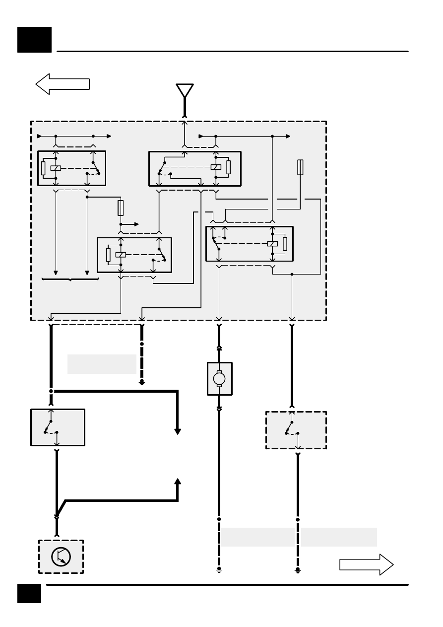
HEATING AND VENTILATION (WITH A/C) (PETROL)

K4

12

CIRCUIT DIAGRAM

F 37

30 A

X312
Pressure Switch
2

[1]

< 13 Bar
(189 psi)

[2]

> 17 Bar
(247 psi)

P125a
Engine
Compartment
Fuse Box

[13] A/C

Condenser
Fan 1 Relay

[14] A/C

Condenser
Fan 2 Relay

[18] A/C Control

Relay

[19] Engine Main

Control
Relay

K4-11

RL19

[19]

3

1

2

5

RL13

[13]

1

3

2

5

4

30

F 36

30 A

15

15

RL18

[18]

5

1

2

3

Sequential
Multiport Fuel
Injection (SFI–V8)

RL14

[14]

1

4

2

3

5

4

2

C0570

C

BN

BN

3

C0571

B

S114

E0559

See Ground
Distribution

2

C0576

BR

M121
Right
Condenser
Fan Motor

See Ground
Distribution

1

C0280

2

C0280

B

M

2

C0571

BU

[5]

[4]

3

C0844

S122

B

4

C0844

X315
A/C Dual
Pressure Switch

[4]

< 17 Bar 
(247 psi)

[5]

> 21 Bar 
(305 psi)

Petrol

See Ground
Distribution

8

C0792

Z253
Heating Ventilation and Air
Conditioning Control Unit
(HEVAC)

[2]

2

C0845

[1]

1

C0845

11

C0229

C0067

YB

30

Sequential
Multiport Fuel
Injection (SFI–V8)

E0560

E0560

S139

30

S111

HEATING AND VENTILATION (WITH A/C) (DIESEL)

K4

13

CIRCUIT DIAGRAM

30

F 31

30 A

6

C0574

1

C0025

BN

P125a
Engine
Compartment
Fuse Box

M113
Left Condenser
Fan Motor

2

C0025

D

K4-14

M

Diesel

BN

HEATING AND VENTILATION (WITH A/C) (DIESEL)

K4

14

CIRCUIT DIAGRAM

X312
Pressure Switch
2

[1]

< 13 Bar
(189 psi)

[2]

> 17 Bar
(247 psi)

P125a
Engine
Compartment
Fuse Box

[13] A/C

Condenser
Fan 1 Relay

[14] A/C

Condenser
Fan 2 Relay

[18] A/C Control

Relay

[19] Engine Main

Control
Relay

K4-13

RL19

[19]

3

1

2

5

RL13

[13]

1

3

2

5

4

30

F 36

30 A

15

15

RL18

[18]

5

1

2

3

Diesel

RL14

[14]

1

4

2

3

5

4

2

C0570

D

BN

8

C0792

BN

Z253
Heating
Ventilation and
Air Conditioning
Control Unit
(HEVAC)

3

C0571

B

S114

E0559

See Ground
Distribution

2

C0576

BR

M121
Right
Condenser Fan
Motor

S111

E0560

See Ground
Distribution

1

C0280

2

C0280

B

M

2

C0571

BU

[5]

[4]

3

C0844

S122

E0560

B

4

C0844

X315
A/C Dual Pressure
Switch

[4]

< 17 Bar
(247 psi)

[5]

> 21 Bar
(305 psi)

Diesel

[2]

2

C0845

[1]

1

C0845

11

C0229

C0067

YB

See Ground
Distribution

30

30

F 37

30 A

POWER WINDOWS

L1

CIRCUIT OPERATION

1

CIRCUIT OPERATION

The window lift system will provide one touch or inch
mode on all windows and will have the anti–trap
function (when initialised) on close.

Initialised window operation.

Selection of any* aperture switch, in either direction,
for less than 0.4 seconds shall initiate the “one
touch” mode of operation. That aperture will be
driven in the direction selected until a trap
(obstruction) is detected (close only) or the motor
stalls. This mode will be cancelled by the operation
of the associated switch in the opposite direction. If
the associated aperture switch is operated in the
opposite direction then the window will be driven in
that direction according to the requirements for one
touch/inch mode operation.

* Rear window one touch up is a programmable
feature.

Selection of any aperture switch for greater than 0.4
seconds will cause that aperture to operate in the
“inch mode”. The aperture will move in the selected
direction until a trap (obstruction) is detected (close
only), the limit of travel is reached or the switch is
released.

All windows will operate independently from each
other and may operate in parallel. In case of conflict
between switches, those in the centre console switch
pack will have priority.

The window lift system will only be active under the
following conditions:

a) while auxiliary is on, ie, the window system will not
be active during crank. Any one touch operations will
be cancelled when ignition 1 turns off during crank.

b) for the first 45 seconds after auxiliary has been
switched off, the one touch up and down functions
will not be available during this time period. If, during
the above 45 second time period, the drivers door is
opened, the window system will remain active for a
further 45 seconds from the door opening or until the
door is closed again, whichever is sooner. If during
either of the 45 second time periods a door lock
signal is received, then the timer will be cancelled
and therefore the window lift system will no longer be
active.

The rear windows can be prevented from being
operated from their local switch by the rear inhibit
switch in the centre console. In the event of a centre
console serial link failure being detected, the local
rear window switches will default to inhibited.

Operation of the driver’s window down switch will
cause the drivers window to move in the down
direction until the switch is released (unless in the
one touch mode), the up switch is operated, or until
a stall condition is detected (i.e. the window is fully
open).

Operation of the drivers window up switch will cause
the window to operate in the close direction until the
switch is released (unless in the one touch mode),
the window down switch is operated, a trap condition
is detected, or until the motor stalls (i.e. the window
is fully closed).

Market Deviations:

a) USA/Canada/Germany:

The system will only be active when the auxiliary
(ignition 1) is on, or for the time between switching
the auxiliary feed off and opening either of the front
doors, but not exceeding 45 seconds.

b) Australia: One touch operation will only be
available for the drivers window.

c) Germany: The back off distance from a trap
condition will be 200mm.


Content   ..  204  205  206  207   ..