Range Rover 2. Electrical Manual - part 188
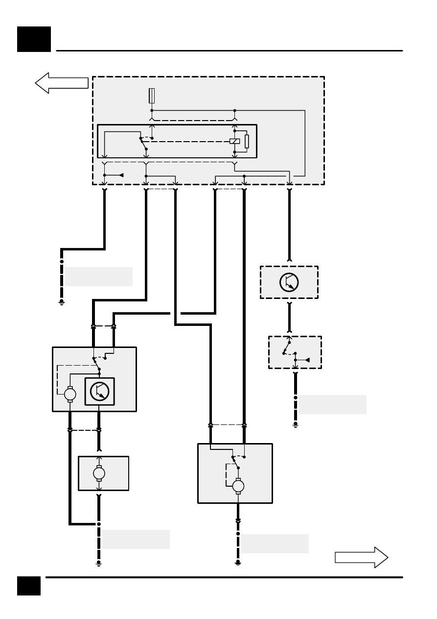
WASH/WIPE
F5
4
CIRCUIT DIAGRAM
REV: 08/99
15
F 25
20 A
RL11
[11]
2
3
1
5
5
C0571
4
5
4
1
2
C0574
P125a
Engine
Compartment
Fuse Box
[11] Headlamps
Wash/Wipe
Relay
LGR
NU
LGU
LGU
B
S101
E0557
See Ground
Distribution
S111
E0560
See Ground
Distribution
4
6
C1282
M
1
C0874
2
C0874
M
[1]
[2]
4
C0853
1
C0853
M
[1]
[2]
3
C0854
2
R
B
4
B
B
2
1
C0854
S114
E0559
See Ground
Distribution
Z238
Body Electrical
Control Module
(BECM)
M110
Headlamp Wash
Pump
C0576
C0570
M157
Right Headlamp
Wiper Motor
[1]
Run
[2]
Park
M156
Left Headlamp
Wiper Motor
[1]
Run
[2]
Park
3
C1278
U
4
C0041
3
C0041
B
X145
Main Lighting
Switch
[2]
Headlamps
E0562
See Ground
Distribution
S208
[2]
0
YB
RB
B
YB
RB
W