Range Rover 2. Electrical Manual - part 170
AUTOMATIC GEARBOX
B7
6
CIRCUIT DIAGRAM
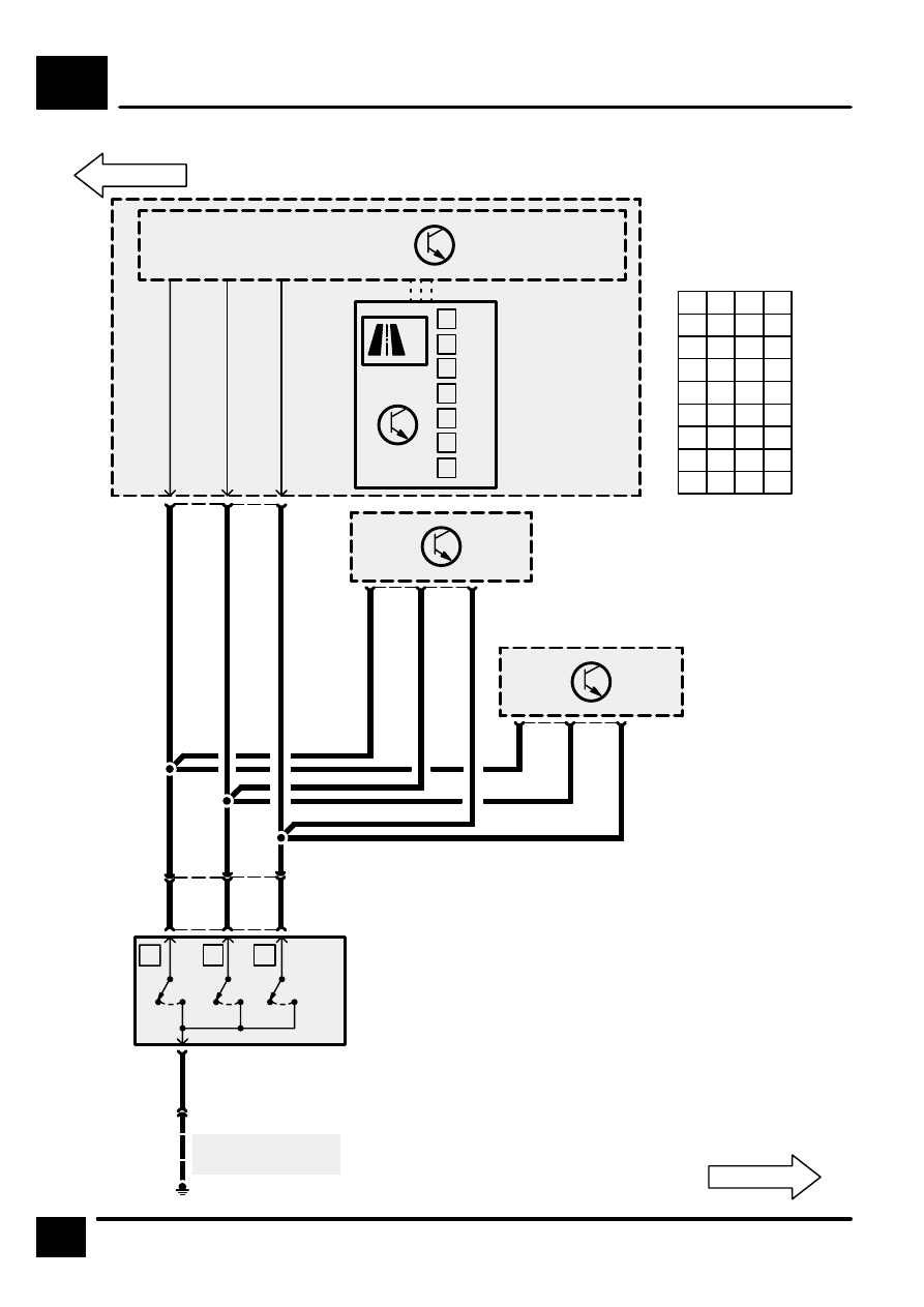
UB
Z254
’H’ Gate Sensor
Module
O
O
O
O
O
O
O
Note! Status of X,
Y, Z Switches
only affects Red
Illumination dots
P
R
N
D
3
2
1
X
Y
Z
S610
S609
18
C1287
9
UG
UP
8
UB
Z238
Body Electrical
Control Module
(BECM)
S608
UP
UG
See Ground
Distribution
E0808
6
C0244
BG
2
C0988
C0745
X
Y
Z
[1]
[2]
[3]
0
0
0
3
C0244
2
1
4
5
C0745
C0988
33
C1321
14
50
Z255
Auto Gear Box
Control Unit
HI
P
0
1
1
R
0
0
1
N
1
0
1
D
1
0
0
3
0
0
0
2
0
1
0
1
1
1
0
Z*
1
1
1
X
Y
Z
1 =
0 =
* =
Switch Open
Switch Closed
Fault
36
8
37
C1320
Diesel
Petrol
3
5
C0675
4
3
X294
Gear Box
Position Switch
[1]
X Switch
[2]
Y Switch
[3]
Z Switch