Range Rover 2. Electrical Manual - part 156
DIESEL
A6
8
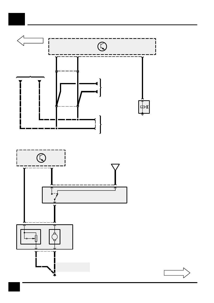
CIRCUIT DIAGRAM
2 C1289
M
[1]
[2]
Z134
Fuel Pump Module
[1]
Fuel Level Sensor
[2]
Fuel Pump
[1]
0
WP
2
3 C0123
WU
4 C0204
GB
Z238
Body Electrical
Control Module
(BECM)
1
3 C0204
2
WO
D
A6-7
1
C0123
X135
Inertia Fuel
Shut–Off Switch
[1]
Impact
See Ground
Distribution
E0559
10
42
PR
Z132
Engine Control
Module (ECM)
27
16
GR
Data Link
Connector
17
C0203
C0448
KR
LG
K
Data Link
Connector
15
C0067
16
C0229
LGR
KR
S214
7
C0040
S213
15
LGR
LGR
X318
Data Link
Connector
(OBDII)
3 C0411
G
1 C0198
K111
Fuel Shut–Off
Solenoid