Range Rover 2. Electrical Manual - part 70
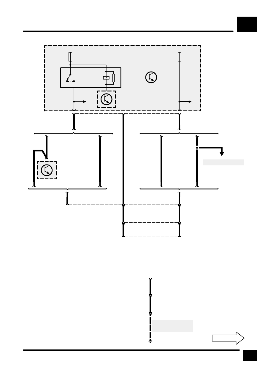
TRAILER AUXILIARY SOCKET
P1
3
CIRCUIT DIAGRAM
E367
See Ground Dis-
tribution
S357
1
C365
C370
U
1
C371
C372
U
3
C376
X172
Trailer Auxiliary
Socket
1
6
C376
3
C370
C365
2
4
3
C372
C371
2
G
R
Z177
Left Antenna Am-
plifier
1
C364
WO
WO
GN
KO
KO
See Fuse Details
KO
4
C361
5
1
30
F 8
30 A
RL7
30
F 14
20 A
Z238
Body Electrical
Control Module
(BECM)
Japan
Except Japan
KO
WO
Base
Trim Level 3
Japan
Except Japan
Base
Trim Level 3
Battery +
Reverse Lamps
Chassis
Not used