Range Rover 2. Electrical Manual - part 31
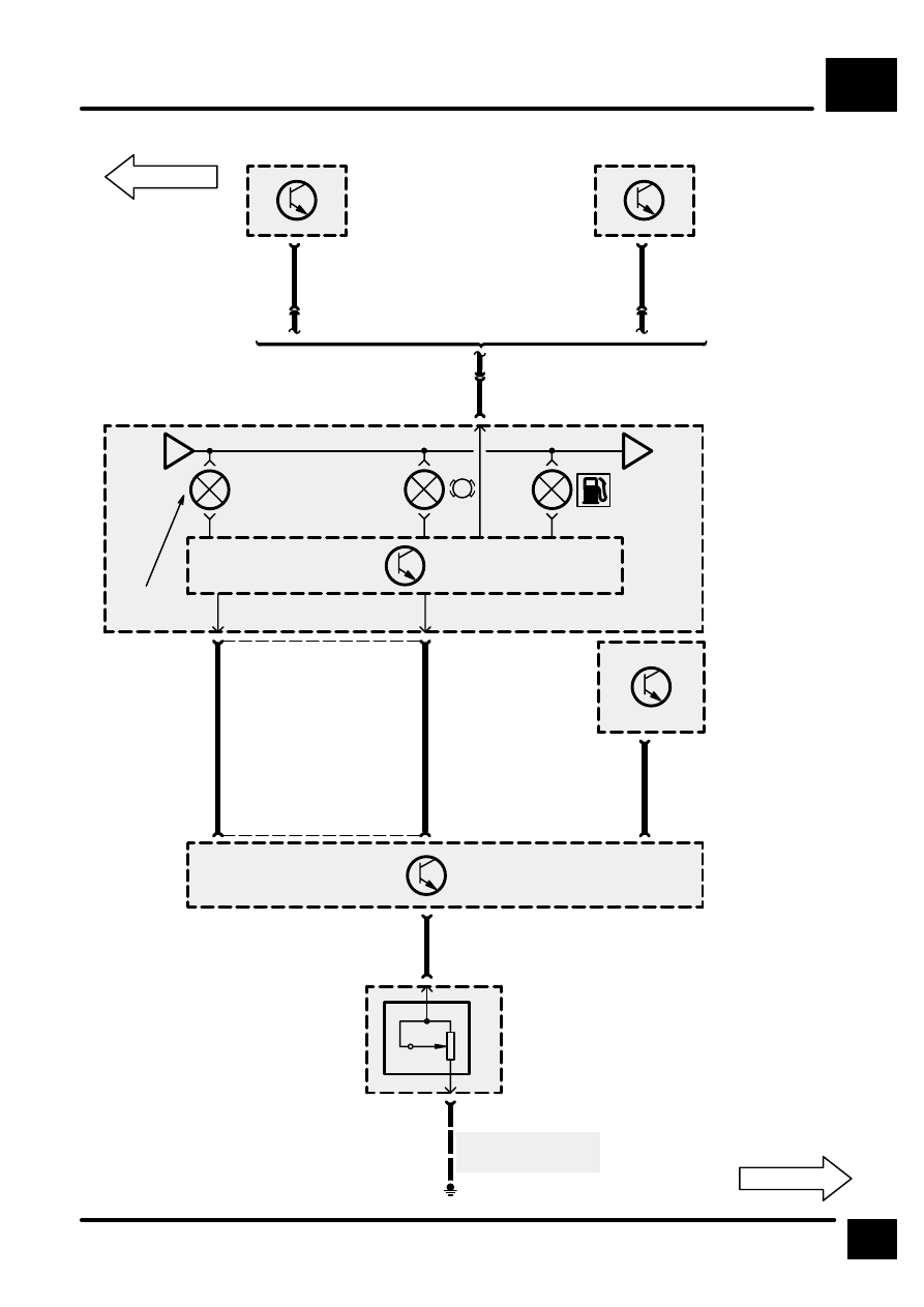
WARNINGS AND INDICATORS
E2
5
CIRCUIT DIAGRAM
2
C505
GU
4
C106
C506
Z132
Engine Control
Module (ECM)
49
C572
GU
24
C121
C571
Z132
Engine Control
Module (ECM)
8
C202
C102
Z142
Instrument
Cluster
[15] Control Unit
and Mess-
age Centre
Display
A
E2-4
B
E2-6
SERVICE REMINDER
INDICATOR (SERVICE
ENGINE)
30
30
30
[15]
NAS
19
C242
Petrol
Diesel
9
C242
16
[1]
Z134
Fuel Pump Module
[1]
Fuel Level Sen-
sor
C110
1
C110
2
E167
8
16
C256
28
C116R
YG
Z108
Anti–Lock Brake
System ECU
11
C114
GB
10
C114
C116L
LHD
RHD
Y
S
Z238
Body Electrical
Control Module
(BECM)
B
See Ground Dis-
tribution