Range Rover Body Repair Manual - part 37


  Index      Land Rover     Range Rover - Body Repair Manual 1996 year


Search            


Content   ..  35  36  37  38   ..


Range Rover Body Repair Manual - part 37


CHASSIS AND BODY

73

REPAIR

WINDSCREEN

Service repair no - 76.81.01

NOTE: The following equipment is
required:

masking tape;
sharp knife;
reciprocating blade, powered cutting knife*, or
cutting wire and handles;
suction lifters;
windscreen repair kit;
sealer applicator gun.

* A reciprocating blade cutting tool, such as ’FEIN
Special Cutter’, is recommended for this operation. A
flat blade, with an effective length of at least 25mm
and a ’U’ shaped blade of at least 30mm is required.

CAUTION: Extreme care is necessary to
ensure that paintwork and trim does not
become damaged during the removal

process.
Particular care should be taken when using
cutting wire and handles to avoid damage to seal
along leading edge of fascia.

WARNING: Wear protective gloves when
handling glass, solvents and primers.

Remove

1. Remove interior mirror.

See this section.

2. Remove plenum panels.

See HEATING AND

VENTILATION, Repair.

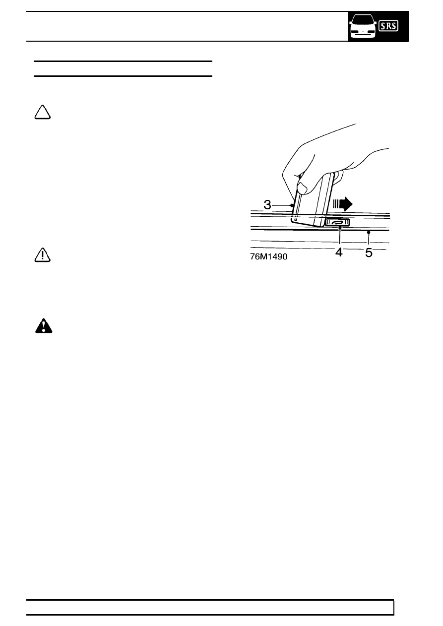
3. Insert a thin plastic strip, such as a credit card,

between windcreen upper finisher and roof
panel.

4. Disengage 8 clips securing upper finisher by

sliding clips towards left hand side of vehicle.

5. Remove upper screen finisher.

76

CHASSIS AND BODY

NEW RANGE ROVER

74

REPAIR

6. If fitted, disconnect heating element multiplugs.

Disconnect heating element earth wire. Tape
heater connections onto windscreen to prevent
fouling during removal procedure.

7. Mask around windscreen aperture to protect

paintwork.

8. Fit protective cover over fascia and bonnet.

Removal Using Reciprocating Blade Tool

9. Cut through P.U. adhesive along sides of screen

using flat blade.

10. Using a ’U’ shaped blade, cut through adhesive

bead along upper and lower edges of screen.

CAUTION: Access to adhesive around
lower screen supports is restricted.
Manoeuvre blade to cut as much sealant

from around screen supports as possible.

11. Attach suction lifters to glass. With assistance,

cut through remaining sealant around screen
supports using a sharp knife.

12. With assistance, remove windscreen glass.

Removal Using Cutting Wire and Handles.

13. Remove both ’A’ post finishers.

See this

section.

14. Remove both sun visors.

See this section.

15. Remove map/courtesy lamp assembly.

See

ELECTRICAL, Repair.

CHASSIS AND BODY

75

REPAIR

16. Mask along leading edge of headlining.
17. Using a sharp knife, cut through P.U. sealer at

side of screen, towards lower corner.

18. Insert cutting wire through knife cut and fit

handles, as shown, with approximately 200 mm
(8 in) of wire between handles.

19. With assistance, wedge tube of handle ’A’

between glass and body, ahead of the cutting
position, and carefully cut the sealer using a
continuous pull on handle ’B’ from the outside.
Cut side and top edges first. Attach suction lifters
and restrain glass as last of sealant is cut.

NOTE: When cutting along lower edge,
manoeuvre wire between glass edge and
screen supports to reduce strain on wire.

20. Attach suction lifters to glass. With assistance,

remove windscreen.

Refit

21. carefully cut old sealer from body flange to

obtain a smooth surface, approximately 2 mm
(1/16 in) thick.

CAUTION: Do not cut down to painted
surface.

22. Inspect supports, renew if damaged.
23. Position screen on felt covered surface.
24. If original screen is to be refitted, cut old sealer

from glass to obtain a smooth surface,
approximately 2 mm (1/16 in) thick.

76

CHASSIS AND BODY

NEW RANGE ROVER

76

REPAIR

CAUTION: Do not cut down to surface of
glass.

25. Position and centralise new windscreen to body.

Apply tape reference marks to aid final fitment.
Remove screen and position to work surface.

26. Apply cleaning solvent to sealing surface of

glass and body flange.

CAUTION: Do not touch cleaned or primed
areas with fingers.

27. Position 5 screen spacer blocks on inside edge

of glass, over cut-out marks in obscuration band.

28. If necessary, peel off backing strip and stick

foam glazing dam along inside surface of glass,
approximately 13 mm (1/2 in) from top edge.

29. Shake primer tins for at least 30 seconds. Apply

body primer to sealing surface of body flange
using supplied applicator.

30. Apply glass primer to sealing surface of glass.

CAUTION: Use a separate applicator for
each primer.

31. Remove lid from sealer cartridge, remove

crystals, pierce membrane and fit pre-cut nozzle.
Fit cartridge to applicator gun.

NOTE: The profile of the nozzle must be
modified slightly to produce the required
bead section.


Content   ..  35  36  37  38   ..