Range Rover. Manual - part 337


  Index      Land Rover     Range Rover P38 - service manual 1995 year


Search            


Content   ..  335  336  337  338   ..


Range Rover. Manual - part 337


NAVIGATION SYSTEM

3

REPAIR

AERIAL - GLOBAL POSITIONING SYSTEM (GPS)

Service repair no - 86.53.05

Remove

1. Disconnect battery earth lead.
2. Open bonnet and cover lower RH ’A’ post to

wing with tape, to prevent clips falling into cavity.

CAUTION: Always protect paintwork when
removing trim finishers.

3. Remove RH windscreen wiper arm.

See

WIPERS AND WASHERS, Repair.

4. With care release RH edge of lower windscreen

finisher from ’A’ post finisher.

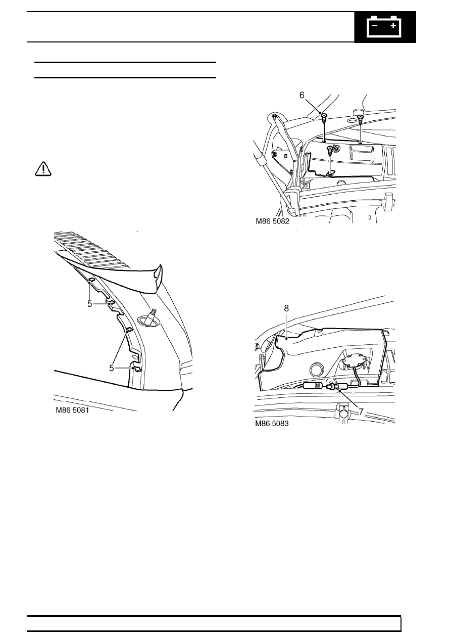
5. Carefully release 4 clips securing lower

windscreen finisher to RH side of windscreen.

6. Remove 3 screws from RH plenum cover.

7. Lift RH plenum cover to gain access to GPS

aerial, disconnect lead from waterproof sleeve.

87

NAVIGATION SYSTEM

NEW RANGE ROVER

4

REPAIR

8. Remove plenum cover from vehicle.
9. Remove 2 screws securing GPS aerial to

plenum cover and separate.

Refit

10. Fit GPS aerial to plenum cover and secure with

screws.

11. Connect GPS aerial lead and cover with

waterproof sleeve.

12. Fit plenum cover to vehicle and tighten screws.
13. Raise lower edge of RH ’A’ post finisher, align

lower windscreen finisher and fit clips.

14. Fit wiper arm assembly.

See WIPERS AND

WASHERS, Repair.

15. Remove tape from RH wing.
16. Connect battery earth lead.

DISPLAY UNIT - NAVIGATION SYSTEM

Service repair no - 86.53.20

Remove

1. Remove radio.

See ELECTRICAL, Repair.

2. Remove instrument binnacle.

See

INSTRUMENTS, Repair.

3. Move both front seats to the fully rearward

position.

4. Remove 2 screws securing electric window

switch pack to centre console and position
switch pack aside.

5. Remove 2 screws securing each side panel to

centre console. Release sprag clips from fascia
switch pack by firmly pulling rearwards. Remove
side panels.

NAVIGATION SYSTEM

5

REPAIR

6. Remove 5 screws securing switch pack to centre

console.

7. Move switch pack forward, disconnect 1 lucar

and 11 multiplugs from switch pack and remove
switch pack.

8. Release 4 clips securing satellite navigation

display unit to switch pack and remove display
unit.

Refit

9. Fit satellite navigation display unit to switch pack

and secure clips.

10. Position switch pack to centre console and

connect lucar and multiplugs.

11. Fit switch pack to centre console and secure

with screws.

12. Fit side panels to centre console and secure

clips and screws.

13. Fit electric window switch pack to centre console

and secure with screws.

14. Fit instrument binnacle.

See INSTRUMENTS,

Repair.

15. Fit radio.

See ELECTRICAL, Repair.


Content   ..  335  336  337  338   ..