Range Rover. Manual - part 214
SUPPLEMENTARY RESTRAINT SYSTEM
17
DESCRIPTION AND OPERATION
OPERATION
All system operations become active when the ignition
switch is turned to position ’II’ and remains operational
when the ignition switch is in the CRANK position.
When the ignition switch is turned on, the SRS
warning lamp illuminates for approximately 5 seconds
then turns off, this indicates that the system is
functional.
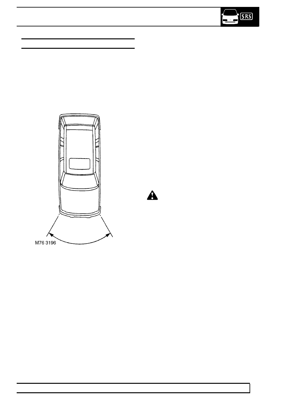
Front impacts
The front airbags and the seatbelt pre-tensioners are
deployed in the event of a frontal impact of sufficient
severity which exceeds the impact trigger threshold.
When the accelerometer and safing sensor in the
SRS diagnostic control unit senses the impact, the
diagnostic control unit triggers the front airbag
modules by firing an igniter. This in turn ignites tablets
of sodium azide which generate a large amount of
Nitrogen gas causing airbag inflation. For vehicles
fitted with a distributed sensing system, an activation
signal is also provided to the DCU from one or both of
the front crash sensors.
The DCU simultaneously triggers the seatbelt
pre-tensioner operation. This is achieved by activating
a propellant which acts on the seatbelt inertia reel
causing an increase in the tension of the seatbelt to
restrain the occupant in a safe and secure position
during airbag deployment. The seatbelt pre-tensioners
are armed by the safing sensor which have a faster
deployment time than the front airbags, so that the
occupant is held in the restrained position before the
airbag is fully inflated.
The diagnostic control unit (DCU) is able to distinguish
between rough road conditions and a frontal collision.
If the DCU’s main sensor (or front crash sensors for
distributed systems) detects a frontal collision of
sufficient severity and it is confirmed by the safing
sensor, the DCU sends a fire signal to the airbag
module and seatbelt pre-tensioner initiators.
The front airbags offer additional protection to the
front seat occupants. The front airbags are fully
inflated, then as the occupant moves into the airbag it
immediately discharges the gas from vent holes to
provide progressive deceleration and reduce the risk
of injuries.
WARNING: Certain SRS system
components, MUST be renewed after the
airbags and seatbelt pre-tensioners have
been deployed. REFER to SRS Component
Replacement Policy in this section of the
Workshop Manual.