Range Rover. Manual - part 153
ZF AUTO
13
DESCRIPTION AND OPERATION
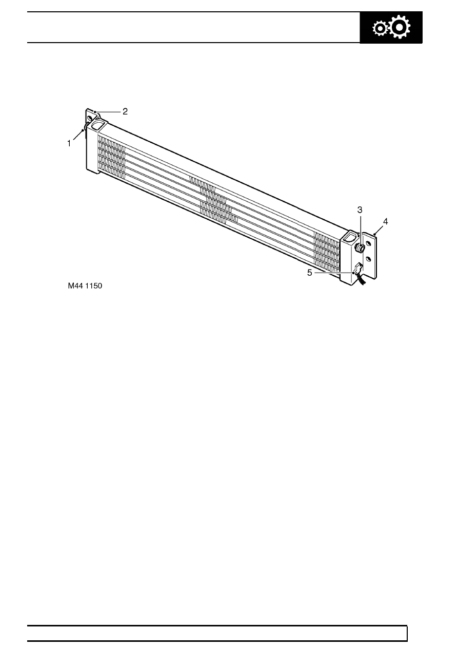
Fluid Cooler
1. Outlet connection
2. Fixing bracket
3. Inlet connection
4. Fixing bracket
5. Temperature sensor
Transmission fluid from the gearbox is circulated
through a cooler located at the front of the radiator.
Fluid lines from the transmission are connected to
each end tank of the fluid cooler. A temperature
sensor on the LH end tank provides the instrument
pack with an input of transmission fluid temperature. If
the temperature exceeds between 120 and 130
°
C
(248
°
F and 266
°
F), the instrument pack message
centre displays ’GEARBOX OVRHEAT’. The message
remains displayed until the temperature of the fluid
returns to between 82 and 88
°
C (180
°
F and 190
°
F).
EAT ECU
The EAT ECU operates the solenoid valves in the
gearbox to provide automatic control of gear shifts
and torque converter lock-up. The EAT ECU is
attached to a bracket which is secured to the cabin
floor below the LH front seat.
Diesel vehicles from 95MY and petrol vehicles up
to 99MY
A 55 pin connector links the EAT ECU to the vehicle
wiring. Software in the ECU monitors hard wired
inputs and exchanges information via hard wired
connections with the ECM, BeCM and instrument
pack.
Petrol vehicles from 99MY
A 75 pin connector links the EAT ECU to the vehicle
wiring. Software in the EAT ECU monitors hard wired
inputs and exchanges information with the ECM on a
Controller Area Network (CAN) bus to determine gear
shift and torque converter lock-up requirements.
Resultant control signals are then output to the
gearbox solenoid valves.