Range Rover. Manual - part 87


  Index      Land Rover     Range Rover P38 - service manual 1995 year


Search            


Content   ..  85  86  87  88   ..


Range Rover. Manual - part 87


LAND ROVER V8

15

DESCRIPTION AND OPERATION

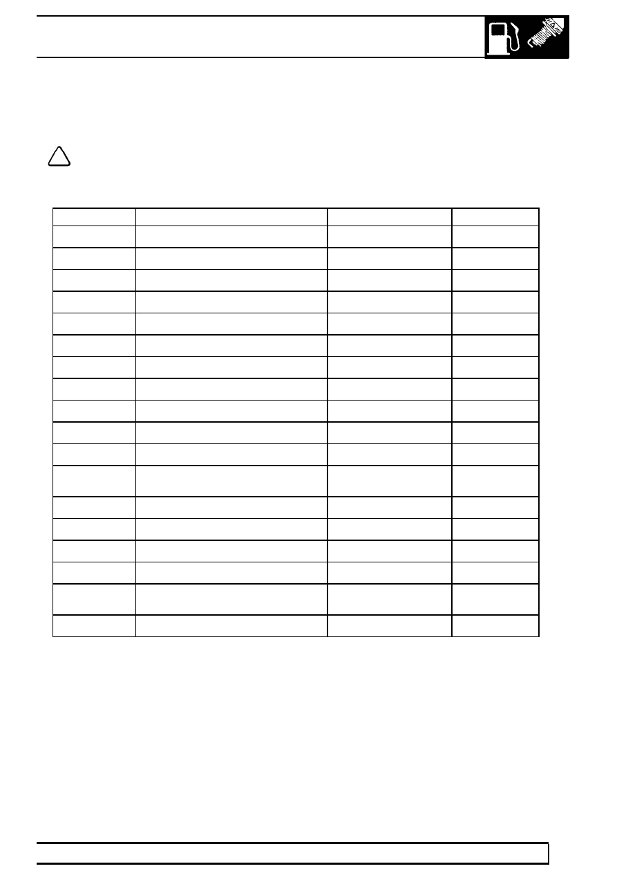
18-pin black connector (C509):

This connector is used primarily for ECM power and earth connections.

NOTE: Voltages and other measurements given are approximations only. Actual values will
depend on particular specification and will be affected by accuracy and calibration of the
measurement tool used and impedances caused by harness wiring etc.

ECM pin details for Connector C509:

Pin No.

Description

Input/Output

Voltage

1

Coil driver - Cylinders 5 & 8

Output

0 - 12V

2

Not used

-

-

3

Not used

-

-

4

Throttle Position Sensor

Output

5V supply

5

ECM to chassis ground

Ground

0V

6

Not used

-

-

7

Main relay supply

Input

0 - 12V

8

Ignition sense

Input

0 - 12V

9

ECM to chassis ground

Ground

0V

10

ECM to chassis ground

Ground

0V

11

Crankshaft (CKP) sensor -ve

Ground

0V

12

Crankshaft (CKP) sensor +ve

Analogue input

18V (average)

at 480Hz

13

Coil driver - Cylinders 2 & 3

Output

0 - 12V

14

Coil driver - Cylinders 1 & 6

Output

0 - 12V

15

Coil driver - Cylinders 4 & 7

Output

0 - 12V

16

ECM to chassis ground

Ground

0V

17

Main relay control

Output

switched to

ground

18

Not used

-

-

19

FUEL SYSTEM

NEW RANGE ROVER

16

DESCRIPTION AND OPERATION

36-pin red connector (C507):

This connector is used primarily for sensor inputs to the ECM.

NOTE: Voltages and other measurements given are approximations only. Actual values will
depend on particular specification and will be affected by accuracy and calibration of the
measurement tool used and impedances caused by harness wiring etc.

ECM pin details for Connector C507:

Pin No.

Description

Input/Output

Voltage

1

Rough road detected

Input

0 -12V

2

Camshaft position (CMP) sensor

Input (2 pulses per

engine revolution)

12V (average)

3

Not used

-

-

4

Transfer box (Low range detected)

Input

0 - 12V

5

Not used

-

-

6

Not used

-

-

7

Fuel level

Input (out of range and

validity check only)

0 - 12V

8

HO

2

S Bank B Upstream

Input

0V (Rich) - 5V

(Lean)

9

Not used

-

-

10

Knock sensor ground

Ground

0V

11

Knock sensor A

Input

Voltage signal

proportional to

level of knock

detected

12

Knock sensor B

Input

Voltage signal

proportional to

level of knock

detected

13

Air temperature sensor

Input

1 k-ohm to 1.3

k-ohm at 40

°

C

(140

°

F)

14

Coolant temperature sensor

Input

4.7V at -30

°

C

(-22

°

F) to

0.25V at 130

°

C

(266

°

F); 2.0V

at 40

°

C (104

°

F)

15

Throttle position sensor

Input

0 to 5V (0.6V at

idle; 4.5V

typical max.)

16

Mass air flow (MAF) Sensor

Analogue input

0 to 5V (1.4V at

idle)

17

HO

2

S sensor Bank A Downstream

Input

0V (Rich) - 5V

(Lean)

LAND ROVER V8

17

DESCRIPTION AND OPERATION

ECM pin details for Connector C507 continued:

Pin No.

Description

Input/Output

Units

18

Park / Neutral Switch

Input

0V

(Park/Neutral) -

12V (Drive)

19

Not used

-

-

20

Diagnostic ’L’ Line

Bi-directional

Serial 0 - 12V

21

Heated front windshield

Output

0V or 12V

22

Not used

-

-

23

Diagnostic ’K’ Line

Bi-directional

Serial 0 - 12V

24

Not used

-

-

25

Not used

-

-

26

Immobilization

Input

Serial 0 - 12V

(366 baud)

27

Vehicle speed

Input

PWM 0 - 12V

(8000 pulses /

mile)

28

A/C request

Output

0V or 12V

29

Condenser cooling fan request

Input

0V or 12V

30

Fuel Pressure sensor (from 97.5 MY)

Input

1 k-ohm to 1.3

k-ohm at 40

°

C

(140

°

F)

31

Ignition Retard Request (EAT ECU)

Input

12V PWM

32

HO

2

S sensor

Ground

0V

33

HO

2

S sensor Bank B Downstream

Input

0V (Rich) - 5V

(Lean)

34

HO

2

S sensor Bank A Upstream

Input

0V (Rich) - 5V

(Lean)

35

Fuel temperature sensor

Input

1 k-ohm to 1.3

k-ohm at 40

°

C

(140

°

F)

36

Sensor ground

Ground

0V

19

FUEL SYSTEM

NEW RANGE ROVER

18

DESCRIPTION AND OPERATION

36-pin black connector (C505):

This connector is used primarily for outputs to actuators and sensors driven by the ECM.

NOTE: Voltages and other measurements given are approximations only. Actual values will
depend on particular specification and will be affected by accuracy and calibration of the
measurement tool used and impedances caused by harness wiring etc.

ECM pin details for Connector C505:

Pin No.

Description

Input/Output

Units

1

A/C grant

Output

0V or 12V

2

Fuel used

Output

Serial 0 - 12V

(12000 pulses

per litre)

3

Condenser cooling fan

Output drive

Switch to

ground

4

Not used

-

-

5

Not used

-

-

6

Canister vent solenoid (from 97.5 MY)

Output

0 - 12V

7

Not used

-

-

8

Not used

-

-

9

Not used

-

-

10

Not used

-

-

11

Injector - Cylinder 3

Output

0 - 12V

12

Not used

-

-

13

Injector - Cylinder 1

Output

0 - 12V

14

Not used

-

-

15

IACV-D Stepper motor

Output

stepped by

sequentially

changing

voltage polarity

16

IACV-B Stepper motor

Output

stepped by

sequentially

changing

voltage polarity

17

Injector - Cylinder 6

Output

0 - 12V

18

Injector - Cylinder 8

Output

0 - 12V

19

Purge valve

Output

0 - 12V (100

Hz)

20

Not used

-

-


Content   ..  85  86  87  88   ..