Frelander 2. Manual - part 652


  Index      Land Rover     Land Rover Frelander 2 - service repair manual 2006-2010 year


Search            


Content   ..  650  651  652  653   ..


Frelander 2. Manual - part 652


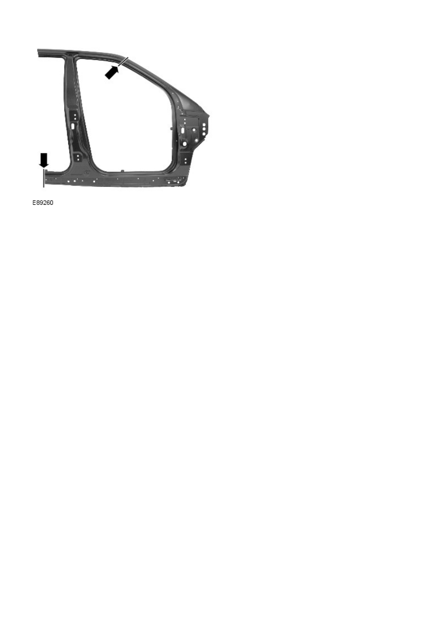
16. MIG weld the butt joints at the A-Pillar and rocker panel.

17. Dress all welded joints.
18. The installation of associated panels and mechanical

components is the reverse of removal.

Side Panel Sheet Metal Repairs - A-Pillar Outer Panel

Removal and Installation

Removal

CAUTION: The A-Pillar outer panel must be MIG slot brazed to the reinforcement, which is DP600, (Dual Phase steel).

MIG plug welds / spot welds, must not be used.

• NOTE: The A-Pillar outer panel is serviced as a separate weld-on panel. The fender mounting bracket is serviced

separately.

• NOTE: There are NVH elements attached inside this panel; they are not serviced on the new panel. If damaged, new

element(s) will be required.

1. The A-Pillar outer panel is replaced in conjunction with:

Front bumper cover

Hood

Front fender

Front door

Instrument panel

Windshield glass

Headliner

2. For additional information relating to this repair procedure

please see the following:

For additional information, refer to: 

Body and Frame

 (501-26

Body Repairs - Vehicle Specific Information and Tolerance

Checks, Description and Operation) /

Standard Workshop Practices

 (100-00 General Information,

Description and Operation).

3. Remove the hood.
4. Remove the front fender.
5. Remove the front door.

For additional information, refer to: 

Front Door

 (501-03 Body

Closures, Removal and Installation).

6. Remove the headliner.

For additional information, refer to: 

Headliner - Vehicles

Without: Tilting Roof Opening Panel

 (501-05 Interior Trim and

Ornamentation, Removal and Installation) /

Headliner - Vehicles With: Tilting Roof Opening Panel

 (501-05

Interior Trim and Ornamentation, Removal and Installation).

7. Remove the instrument panel.

For additional information, refer to: 

Instrument Panel - TD4

2.2L Diesel

 (501-12 Instrument Panel and Console, Removal

and Installation).

8. Remove the windshield glass.

For additional information, refer to: 

Windshield Glass

 (501-11

Glass, Frames and Mechanisms, Removal and Installation).

9. Remove the upper and lower door hinges from the pillar, 4 x

bolts.

10. Remove the rocker panel inner trim.
11. Remove the side air curtain module.

For additional information, refer to: 

Side Air Curtain Module

(501-20B Supplemental Restraint System, Removal and

Installation).

12. Remove the front wheel and tire.

For additional information, refer to: 

Wheel and Tire

 (204-04

Wheels and Tires, Removal and Installation).

13. Remove the rocker panel outer moulding.
14. Release and lay aside the front carpet section.
15. Remove the rear carpet section.
16. Remove the roof moulding, front and rear sections.
17. Release and lay aside the wiring harness along the A-Pillar

inner and inner rocker panel.

18. Release and lay aside the insulating material at the inner

bulkhead.

19. Remove the fender mounting bracket:

Mill out 3 spot welds. If not re-using the mounting the

upper spot weld does not have to be removed.

Separate the mounting from the A-Pillar.

Retain the mounting if it is being reused, if not,

discard.

20. Saw cut the old panel at the points illustrated, using the

new panel for reference, ensuring that the new panel

overlaps the panel remaining on the vehicle.

21. Mill out the spot welds.

22. Separate the joints and remove the old panel, also releasing

the NVH element.

Installation

1. Offer up and align the new panel and clamp into position,

overlapping the old panel remaining on the vehicle. Saw cut

through the new and old panels at the points where the MIG

butt joints are to be made.

2. Remove the new panel and the old remnants.
3. Prepare the old and new panel joint surfaces.

4. NOTE: MIG slots should be installed in accordance with the

spacing shown in the illustration. Where this is not possible,

due to the indents in the panel, the slot should be made in the

location of the original spot weld.

Cut slots in the new panel ready for MIG brazing.

5. Offer up the new panel and clamp into position. Check

alignment, if correct, proceed to next step, if not, rectify and

recheck before proceeding.


Content   ..  650  651  652  653   ..