Frelander 2. Manual - part 587


  Index      Land Rover     Land Rover Frelander 2 - service repair manual 2006-2010 year


Search            


Content   ..  585  586  587  588   ..


Frelander 2. Manual - part 587


Flick wipe
Intermittent/Auto (vehicles without/with rain sensor fitted)
Slow wipe
Fast wipe.

The 'Auto' function requires an input from the rain sensor. The rain sensor is mounted on the inner surface of the
windshield and transmits an infra-red signal to determine the amount of water on the outer surface of the windshield. A
value is then transmitted to the CJB over the Local Interconnect Network (LIN) bus.

The CJB also controls operation of the headlamp wash function. For more information, refer to 'Headlamp Washers' below.

The rear screen wiper system operates independently of the windshield wiper system and is controlled by the CJB on
receipt of LIN bus messages from the RH steering column multi-function switch.

• NOTE: The windshield and rear screen washers utilize the same pump meaning only 1 wash function, either front or rear,
can be performed at any one time.

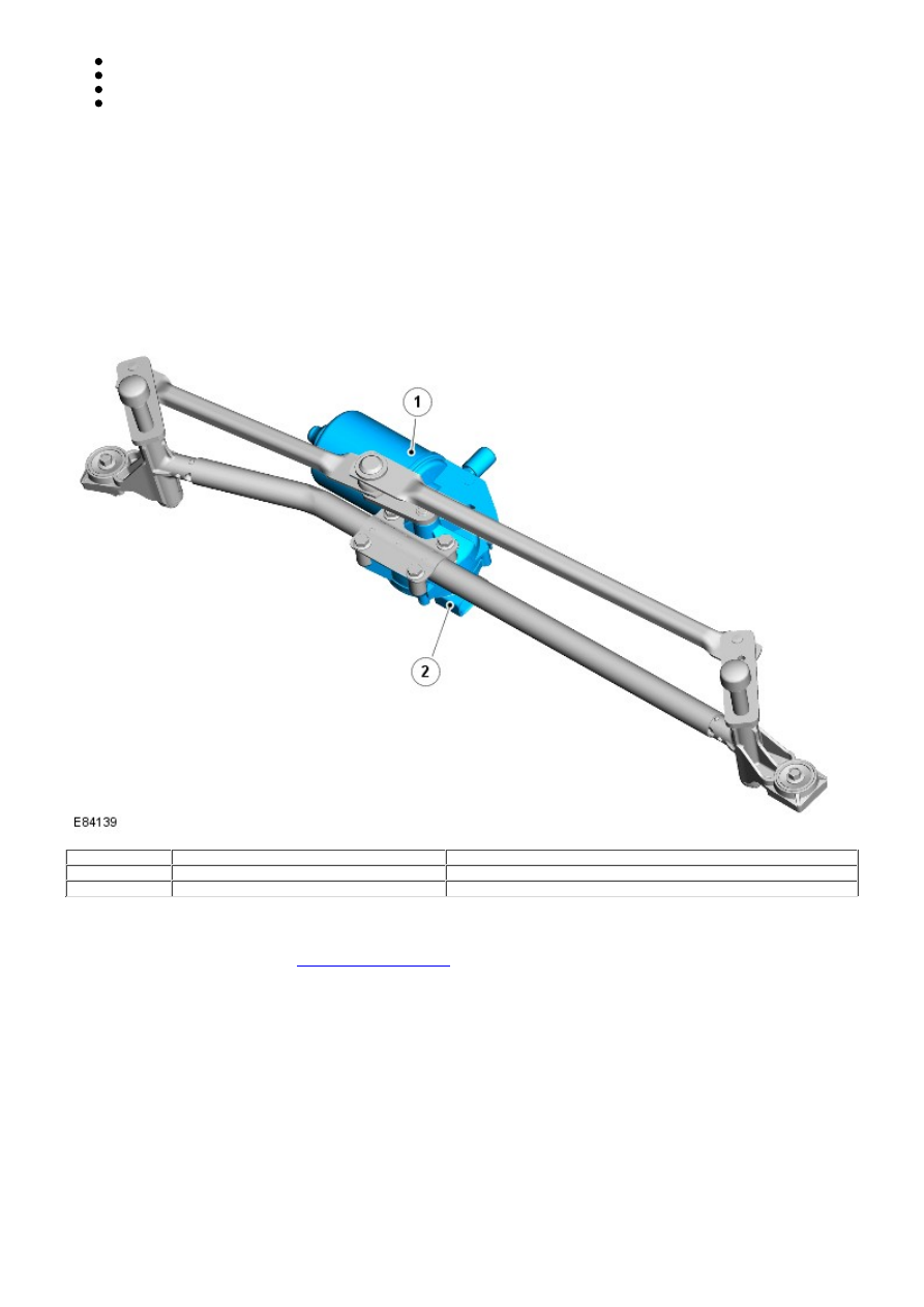
WINDSHIELD WIPER MOTOR

Item

Part Number

Description

1

-

Motor

2

-

Electrical connector

The windshield wiper motor drives a gear wheel via a worm drive attached to the motor spindle. The gear wheel has a
central spigot which provides the attachment point for the motor crank. The motor crank attaches directly to the wiper
linkage link rods and is secured by a single nut. The motor assembly and wiper linkage are a single component and must
be removed or replaced as such.
For additional information, refer to: 

Windshield Wiper Motor

 (501-16 Wipers and Washers, Removal and Installation).

The motor assembly is connected to the vehicle harness by a 4 pin electrical connector. The electrical connector provides 2
battery voltage feeds from the BJB, a wiper park feed from the CJB, and a ground path for the motor assembly.

WINDSHIELD WIPER LINKAGE

Item

Part Number

Description

1

-

RH crank

2

-

RH link rod

3

-

Windshield wiper motor

4

-

Left Hand (LH) link rod

5

-

LH pivot assembly

6

-

LH crank

7

-

Main tube

8

-

RH pivot housing

The windshield wiper linkage comprises a main tube with a pivot housing at each end. The windshield wiper motor is
mounted centrally on the main tube and acts directly on a pair of link rods. The link rods convert the rotary motion of the
motor into a linear, reciprocating motion.

The link rods are connected to the main tube via a crank at each end. The cranks convert the linear, reciprocating motion
of the link rods into a rotary, reciprocating motion of the pivots. This translates to a reciprocating motion of the wiper
blades across the windshield.

The windshield wiper linkage and motor assembly are a single component and must be removed or replaced as such.
For additional information, refer to: 

Windshield Wiper Motor

 (501-16 Wipers and Washers, Removal and Installation).

RAIN SENSOR

The rain sensor is located behind the interior mirror trim casing and sits in a bracket which is bonded to the inner surface
of the windshield. The sensor contains a number of transmitter and receiver diodes which emit and receive infrared light.
By comparing the received light signal against the known transmitted light signal, the rain sensor can determine the
amount of water on the outer surface of the windshield.

• NOTE: = Clean and dry windshield; = W et and dirty windshield

Item

Part Number

Description

1

-

Windshield outer surface

2

-

Optical element

3

-

Transmitter diodes (100% light transmitted)

4

-

Rain sensor

5

-

Receiver diodes (100% light received)

6

-

Water droplets/film

7

-

Receiver diodes (less than 100% light received)

8

-

Lost light

• NOTE: The rain sensor also contains a light sensor. The light sensor is used to control operation of the automatic
headlamps function.
For additional information, refer to: 

Exterior Lighting

 (417-01 Exterior Lighting, Description and Operation).

The rain sensor is connected to the vehicle harness by a 3 pin electrical connector. The electrical connector provides a
power feed from the CJB, a LIN bus connection to the CJB and a ground path.

REAR SCREEN WIPER MOTOR

Item

Part Number

Description

1

-

Motor

2

-

Spindle

3

-

Electrical connector

The single speed rear screen wiper motor is mounted on the inner surface of the liftgate and is secured by 3 bolts. Rubber
bushes isolate the motor assembly from the body to help reduce the transmission of motor operating noise to the liftgate.
The motor is located on a worm drive mechanism, which converts the rotary motion of the motor output spindle into the
required arc for the rear wiper blade.

A 3 pin electrical connector is used to connect the rear screen wiper motor to the vehicle harness. The electrical connector
provides a power feed to the motor from the AJB, a wiper park feed from the CJB, and a ground path.

The AJB contains the rear screen wiper relay. Operation of the relay is controlled by the CJB, which provides feed and
ground paths according to logic contained within its software.

CONTROL DIAGRAM

• NOTE: = Hardwired; = Medium speed CAN bus; = LIN bus


Content   ..  585  586  587  588   ..