Frelander 2. Manual - part 548
1
1
2
1
2
3
1
1
2
3
4
5
6
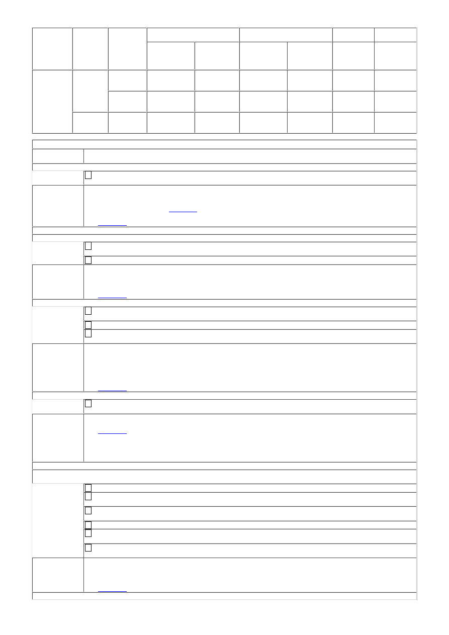
Vehicle
/Year
Cushion /
Backrest
Heater Mat
/ NTC
Resistor
Left Hand Drive
Right Hand Drive
Minimum
Resistance
Maximum
Resistance
Passenger
Side
Connector /
Pin
Driver Side
Connector /
Pin
Passenger
Side
Connector /
Pin
Driver Side
Connector /
Pin
Ohms At
20°C ±10°C
Ohms At
20°C ±10°C
Freelander 2 Cushion
Heater mat C3HS08C-1
and
C3HS08C-4
C3HS03C-1
and
C3HS03C-4
C3HS08C-1
and
C3HS08C-4
C3HS03C-1
and
C3HS03C-4
0,8
1,0
NTC
resistor
C3HS08C-2
and
C3HS08C-3
C3HS03C-2
and
C3HS03C-3
C3HS08C-2
and
C3HS08C-3
C3HS03C-2
and
C3HS03C-3
4 000
10 000
Backrest
Heater mat C3HS08B-1
and
C3HS08B-2
C3HS03B-1
and
C3HS03B-2
C3HS08B-1
and
C3HS08B-2
C3HS03B-1
and
C3HS03B-2
0,5
0,7
PINPOINT TEST A : SEAT HEATER MAT
TEST
CONDITIONS
DETAILS/RESULTS/ACTIONS
A1: CHECK FOR DTC'S
W here possible use the manufacturer approved diagnostic system to review any logged seat heater
mat DTC's
Were any seat heater mat DTC's logged?
Yes
Carry out the help text action for any logged DTC's. Clear the DTC and retest. If DTC's return follow
the tests listed below
GO to A2
.
No
GO to A2
.
A2: MANUAL CHECK
• NOTE: On full power the seat should be hot to touch
If required operate the vehicle air conditioning on full for 10 minutes to reduce the in vehicle ambient
temperature
Operate the seat heater on full power
Does the seat heater operate correctly?
Yes
Clear any stored DTC's and retest. If seat heater operation is correct no further action required
No
GO to A3
.
A3: SHORT CIRCUIT TO GROUND
Refer to the electrical circuit diagrams and the seat heater mat application chart (see above) to
identify the connector
Disconnect the connector
Refer to the electrical circuit diagrams and check the seat heater mat ( heater circuit ) and ( thermal
sensor circuit ) for short circuit to ground
Are either of the circuits short circuit to ground?
Yes
Repair the circuit or replace the seat heater mat as required. Refer to the warranty policy and
procedures manual, or determine if any prior approval programme is in operation, prior to the
installation of a new module/component. Clear any stored DTC's and retest
No
GO to A4
.
A4: CIRCUIT CONTINUITY TEST
Refer to the electrical circuit diagrams and check the seat heater mat ( heater circuit ) for circuit
continuity
Does the seat heater mat heater circuit pass the continuity test?
Yes
GO to A5
.
No
Repair the circuit or replace the seat heater mat as required. Refer to the warranty policy and
procedures manual, or determine if any prior approval programme is in operation, prior to the
installation of a new module/component. Clear any stored DTC's and retest
A5: POWER CONSUMPTION
• NOTE: The seat heater power supply cycles on and off dependant on the seat and cabin temperature and may only
switch on for 5 seconds in 30 seconds
Reconnect the connector
Operate the vehicle air conditioning on full for 10 minutes to reduce the in vehicle ambient
temperature
Refer to the electrical circuit diagrams and check the seat heater mat ( heater circuit ) using a
current clamp
Operate the seat heater on full power
Use the chart above to calculate typical value (V/R=I) (Volts divided by Resistance equals Current
in Amps)
Examples (12 volts / 0.5 ohms =24 amps) (12 volts / 1 ohms = 12 amps) (12 volts / 2 ohms = 6
amps)
Does the seat heater mat consume the correct level of current?
Yes
Clear any stored DTC's and retest. If operation correct, no further action required
No
GO to A6
.
A6: RESISTANCE CHECK