Frelander 2. Manual - part 481
The automatic headlamp system uses a light sensor and the CJB, which are connected via the LIN bus to control the
headlamp functionality.
A light sensor is incorporated in the rain/light sensor located on the inside of the windshield, below the rear view mirror.
The wiper system also uses the rain/light sensor for automatic wiper operation.
For additional information, refer to:
Wipers and W ashers
(501-16 W ipers and Washers, Description and Operation).
The light sensor measures the ambient light around the vehicle in a vertical direction and also the angular light level from
the front of the vehicle. The rain/light sensor uses vehicle speed signals, wiper switch position and the park position of the
front wipers to control the system.
The automatic headlamp operation uses ambient light levels which are monitored by photodiodes incorporated in the
rain/light sensor. The rain/light sensor sends a lights on/off request to the CJB on the LIN bus, which responds by
switching on the low beam headlamps, front side lamps, license plate lamps and rear tail lamps. The automatic headlamps
are activated under the following conditions:
Twilight
Darkness
Rain
Tunnels
Underground or multistoried car parks.
Operation of the automatic headlamps requires the ignition to be on (power mode 6), the lighting control rotary switch to
be in the 'AUTO' position and a lights on request signal from the light sensor.
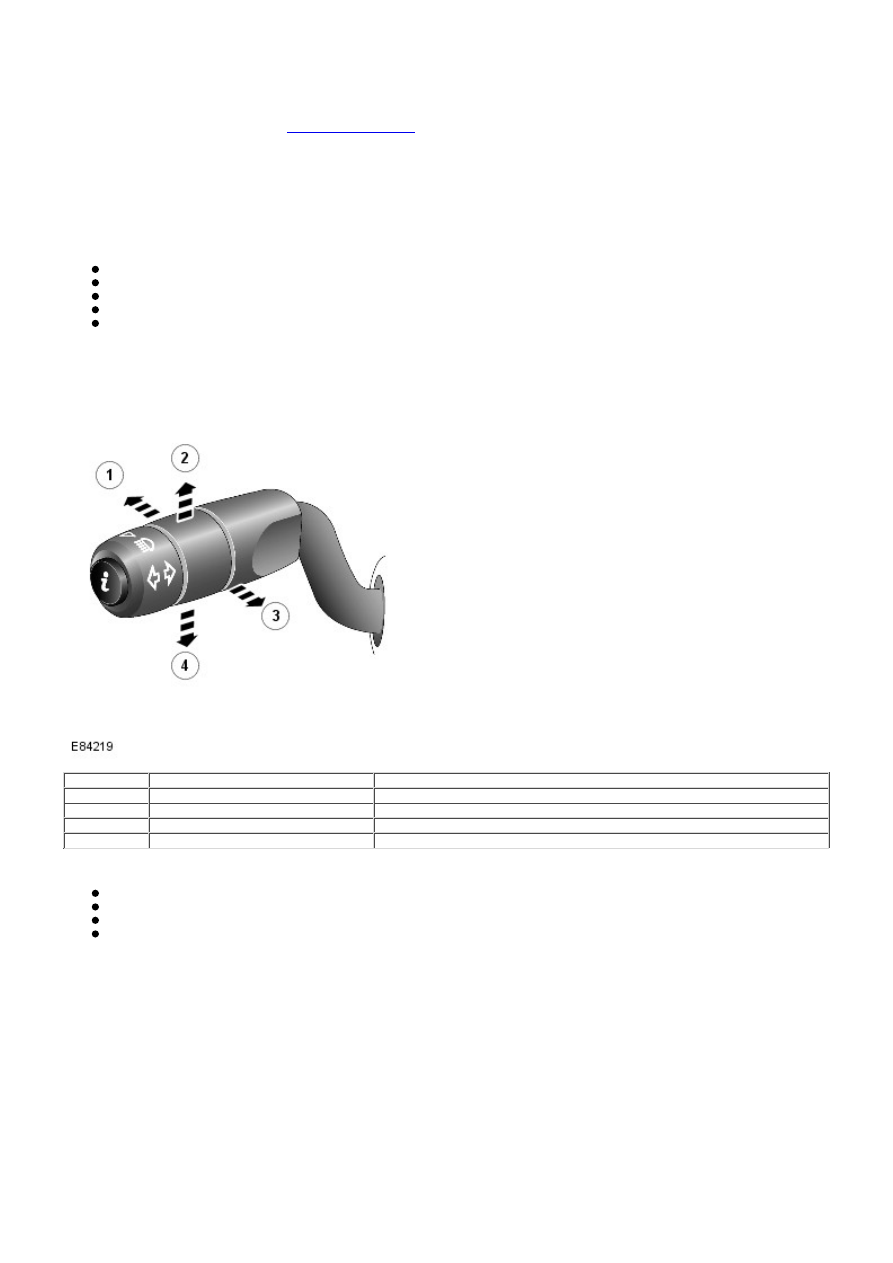
LEFT HAND STEERING COLUMN MULTIFUNCTION SWITCH
Item
Part Number
Description
1
-
High beam
2
-
RH turn signal indicator
3
-
Headlamp high beam flash
4
-
LH turn signal indicator
The steering column multifunction switch is located on the left hand side of the steering column and controls the following
functions:
Headlamp low/high beam
Headlamp high beam flash
Left/right turn signal indicator lamps
Trip computer functions.
The high beam on and flash functions are hardwired to the steering wheel module. W hen the switch is operated in either
position a ground path via the switch is completed for the selected function which is sensed by the steering wheel module.
The steering wheel module then issues a message on the Local Interconnect Network (LIN) bus to the CJB which activates
the selected function.
The turn signal indicator lamps are connected and operate in a similar way with the ground path completed for the
selected function which is sensed by the steering wheel module the module then issues a message relating to the
selected function to CJB which in turn activates the requires turn signal indicator.
HEADLAMP ASSEMBLY
Three headlamp variants are available depending on model specification; halogen, bi-xenon and bi-xenon with Adaptive
Front lighting System (AFS).
The headlamps are sealed units, with scratch resistant polycarbonate lenses bonded to the headlamp body. Two sealed
access covers and a sealed housing provide a watertight environment for the headlamp internal components. To prevent
fogging of the lens and to allow the headlamp unit to 'breath' in response to internal temperature changes, a vent is
located at the outer rear face of the headlamp body. The vent is covered by a Gortex waterproof membrane. This allows