Frelander 2. Manual - part 411
CONTROL DIAGRAM
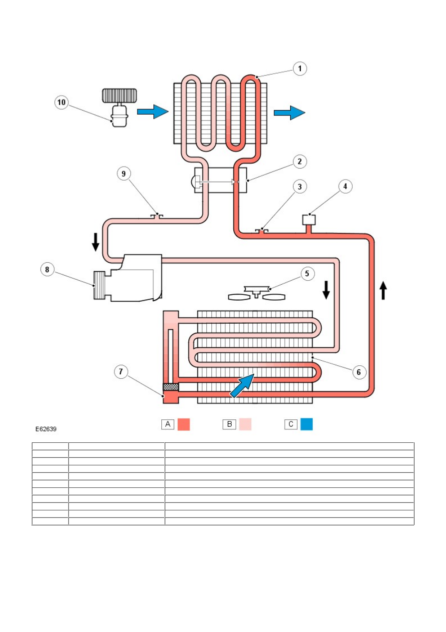
• NOTE: A = Refrigerant liquid; B = Refrigerant vapor; C = Air flow
Item
Part Number
Description
1
-
Evaporator
2
-
Thermostatic expansion valve
3
-
High pressure servicing connection
4
-
Refrigerant pressure sensor
5
-
Engine cooling fan
6
-
Condenser
7
-
Receiver/Drier
8
-
A/C compressor
9
-
Low pressure servicing connection
10
-
Cooling fan
PRINCIPLES OF OPERATION
To accomplish the transfer of heat, the refrigerant is circulated around the system, where it passes through 2
pressure/temperature regimes. In each of the regimes the refrigerant changes state, during which process maximum heat
absorption or dissipation occurs.
The low pressure/temperature regime is from the thermostatic expansion valve, through the evaporator to the compressor.
The refrigerant decreases in pressure and temperature at the thermostatic expansion valve then changes state from a
liquid to a vapor in the evaporator to absorb heat.