Frelander 2. Manual - part 198
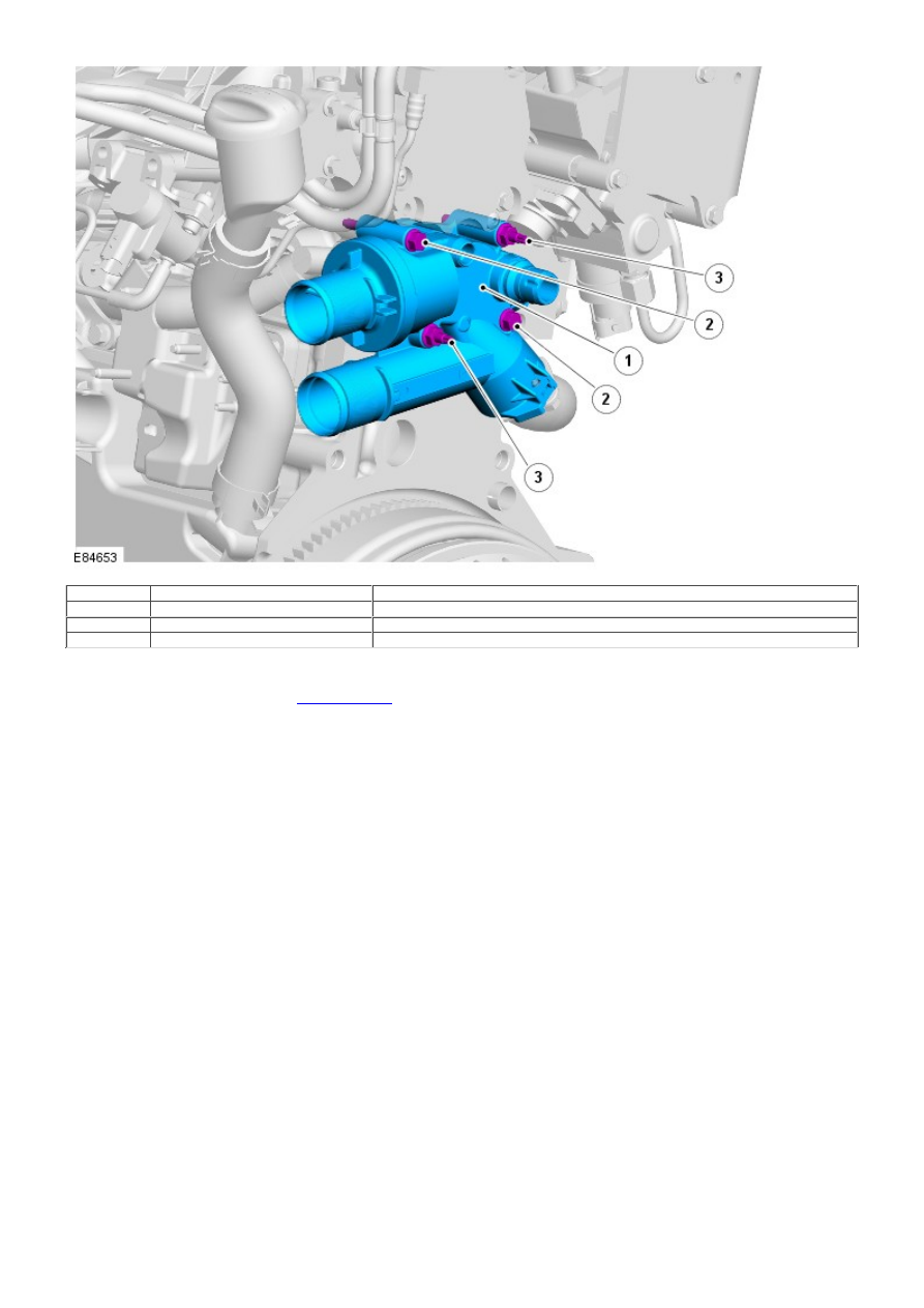
Item
Part Number
Description
1
-
Thermal control module
2
-
Securing bolt (2 off)
3
-
Securing stud and nut (2 off)
The cooling system thermal control module is secured to the rear of the cylinder head by 2 studs with nuts and 2 bolts,
and is sealed to the head with an O-ring. The module contains the cooling system thermostat and forms the junction for
the cooling system hoses.
For additional information, refer to:
Engine Cooling
(303-03B Engine Cooling - TD4 2.2L Diesel, Description and Operation).
Vacuum Pump