Frelander 2. Manual - part 167
Engine - I6 3.2L Petrol - Valve Cover
Removal and Installation
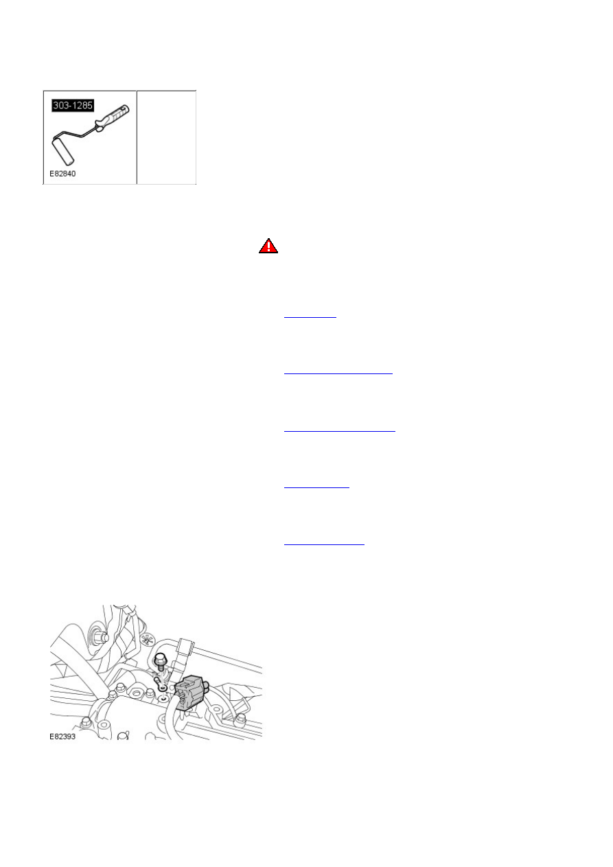
Special Tool(s)
303-1285
Roller, Sealant
Removal
• NOTE: The cylinder head and valve cover are machined as a pair, and cannot be serviced separately.
1.
WARNING: Make sure to support the vehicle with axle stands.
Raise and support the vehicle.
1.
Remove the cover and disconnect the battery ground cable.
Refer to:
Specifications
(414-00 Battery and Charging System - General
Information, Specifications).
2.
Remove the timing component housing.
Refer to:
Timing Components Housing
(303-01A Engine - I6 3.2L Petrol, Removal
and Installation).
3.
Remove the crankcase vent oil separator.
Refer to:
Crankcase Vent Oil Separator
(303-08A Engine Emission Control - I6 3.2L
Petrol, Removal and Installation).
4.
Remove the engine RH mount.
Refer to:
Engine Mount RH
(303-01A Engine - I6 3.2L Petrol, Removal and
Installation).
5.
Remove the 6 ignition coil-on-plugs.
Refer to:
Ignition Coil-On-Plug
(303-07A Engine Ignition, Removal and
Installation).
6.
Disconnect the engine ground cable.
7.
Disconnect the RH front HO2S electrical connector.
8.