Frelander 2. Manual - part 141
Torque: 10 Nm
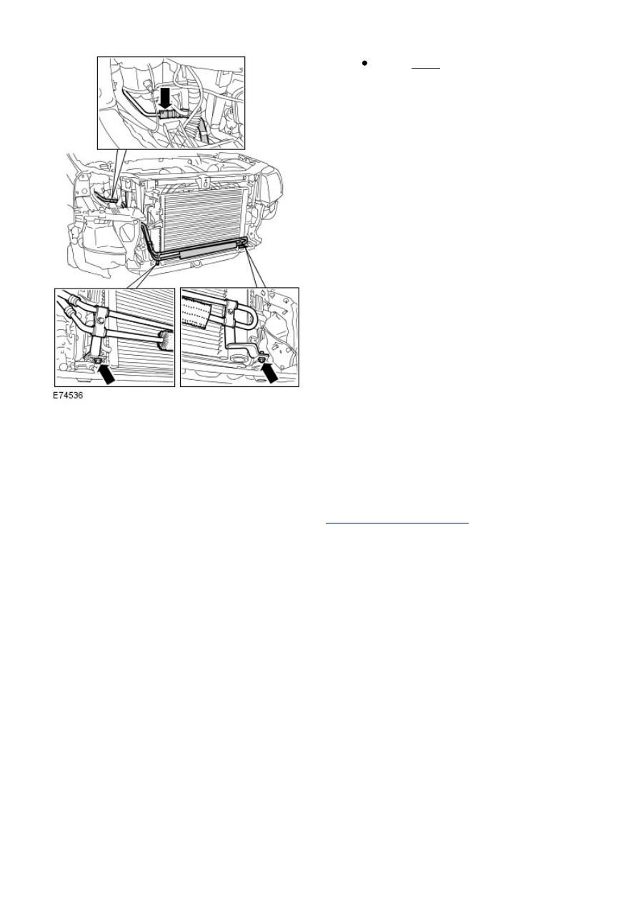
7.
Installation
To install, reverse the removal procedure.
1.
Check and top-up power steering fluid level.
Refer to:
Power Steering System Bleeding
(211-00 Steering System -
General Information, General Procedures).
2.