Frelander 2. Manual - part 134
11.
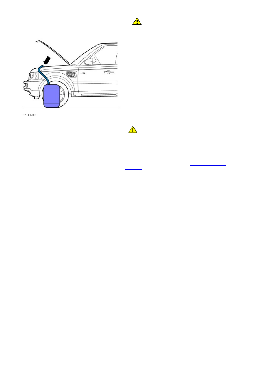
CAUTION: Be prepared to collect escaping fluids.
Remove the suitable pipe to the power steering return hose.
12.
CAUTION: Be prepared to collect escaping fluids.
• NOTE: Note the orientation of the clip.
If a quick release coupling is fitted to the power steering return
hose, connect the power steering fluid return hose to the
coupling by installing the clip.
13. Install a new power steering fluid reservoir.
For additional information, refer to:
Power Steering Fluid
Reservoir
(211-02 Power Steering, Removal and Installation).