Frelander 2. Manual - part 73


  Index      Land Rover     Land Rover Frelander 2 - service repair manual 2006-2010 year


Search            


Content   ..  71  72  73  74   ..


Frelander 2. Manual - part 73


Wheels and Tires - Tire Pressure Monitoring System (TPMS) Rear Antenna

Removal and Installation

Removal

1. 

WARNING: Do not work on or under a vehicle supported only

by a jack. Always support the vehicle on safety stands.

Raise and support the vehicle.

1.

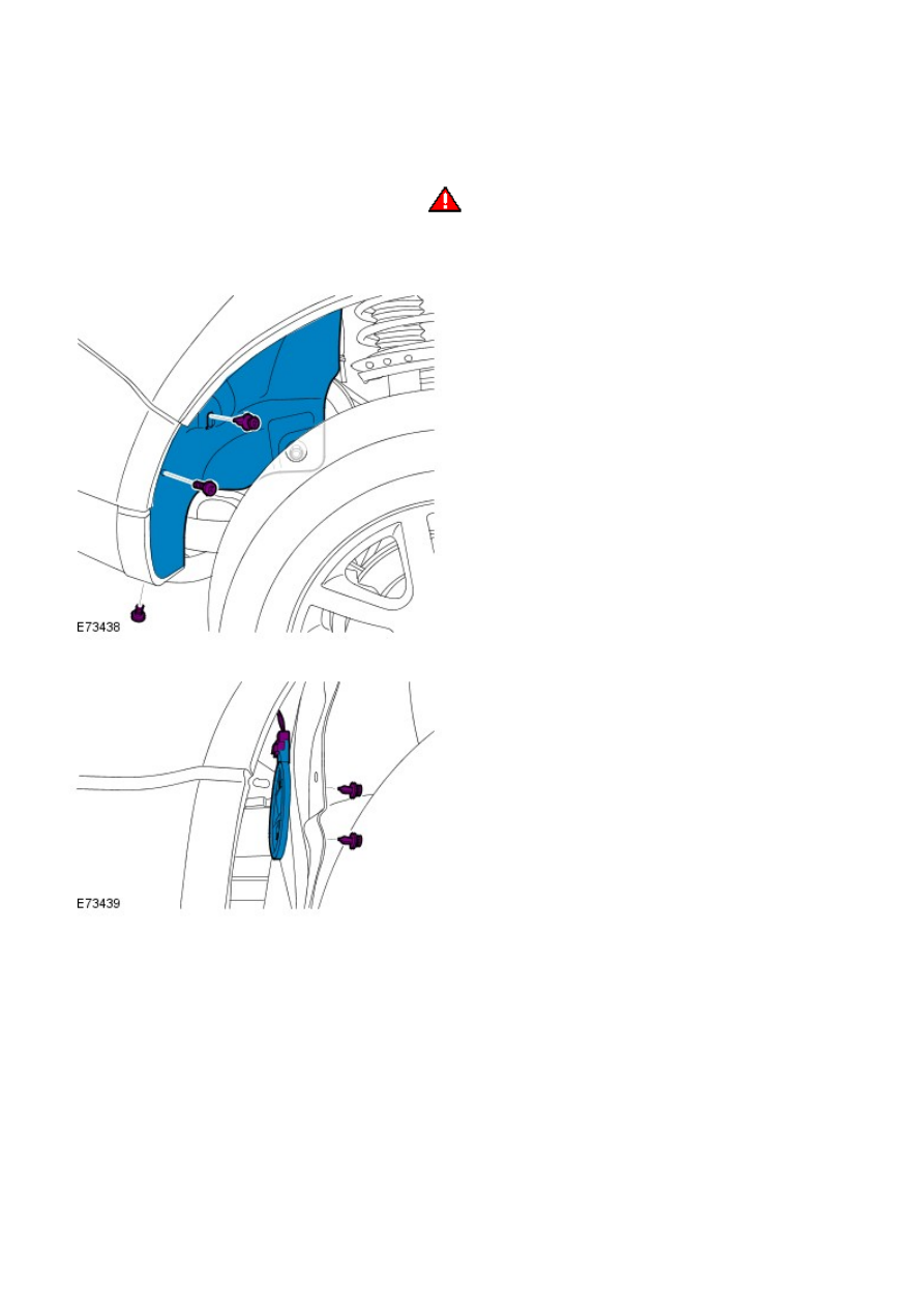
Release the fender splash shield.

2.

Remove the tire pressure antenna.

3.

Installation

To install, reverse the removal procedure.

1.

Initiate a new tire pressure antenna using WDS.

2.

Vehicle Dynamic Suspension - Rear Suspension Height Sensor

Removal and Installation

Removal

• NOTE: This sensor is only fitted to vehicles with Xenon headlamps and is installed on the LH side of the vehicle.

• NOTE: Removal steps in this procedure may contain installation details.

1. 

WARNING: Make sure to support the vehicle with axle

stands.

Raise and support the vehicle.

1.

Remove the wheel and tire.

Refer to: 

Wheel and Tire

 (204-04 W heels and Tires, Removal and

Installation).

2.

Torque: 10 Nm

3.

4.

Installation

To install, reverse the removal procedure.

1.

Using Land Rover approved diagnostic equipment, calibrate the
sensor.

2.

Ride and Handling Optimization - Ride and Handling Optimization

Description and Operation

COMPONENT LOCATION

Item

Part Number

Description

1

-

Terrain Response rotary control

OVERVIEW

The Terrain Response™ system allows the driver to select a program which aims to provide the optimum settings for
traction and performance for the prevailing terrain conditions. The system cannot be switched off. 'Special Programs off' is
the default program and covers all general driving conditions. Three specific terrain programs are selectable to cover all
terrain surfaces.

The system is controlled by a rotary control located on the center console, forward of the transmission selector lever. The
rotary control allows the selection of one of the following 4 programs:

Special programs off
Grass/Gravel/Snow
Mud/Ruts
Sand.

The rotary control can be rotated through 360 degrees or more in either direction and selects each program in turn. When
Terrain Response is fitted to a vehicle, a hi-line instrument cluster will also be fitted which will display the selected
program in the message center.

The Terrain Response system uses a combination of a number of vehicle sub-systems to achieve the required vehicle
characteristics for the terrain selected. The following sub-systems are used in the Terrain Response system:

Engine management system
Automatic transmission (if fitted)
Active on-demand coupling
Brake system (ABS/DSC/ETC/HDC functions).

The rotary control switch pack also contains the Terrain Response control module. The control module detects the selection
made on the rotary control and transmits a signal on the high speed Controller Area Network (CAN) bus which is received
by each of the sub-system control modules. Each of the affected control modules contain software which applies the
correct operating parameters to their controlled system for the Terrain Response program selection made. They also
provide feedback for the selected program so that the Terrain Response control module can check that all systems have
changed to the correct operating parameters.

Information is displayed in the instrument cluster message center which informs the driver of improvements which can be
made to the vehicle operating parameters to optimize the vehicle for the prevailing conditions.


Content   ..  71  72  73  74   ..