Freelander 1. Manual - part 198


  Index      Land Rover     Freelander 1 - service manual 2002 year


Search            


Content   ..  196  197  198  199   ..


Freelander 1. Manual - part 198


RESTRAINT SYSTEMS

REPAIRS

75-11

Air bag - steering wheel

$% 76.74.01

Remove

WARNING: It is imperative that before any 
work is undertaken on the SRS system the 
appropriate information is read thoroughly.

WARNING: When removing, testing or 
installing an airbag module, do not lean 
directly over it.

1. Make the SRS system safe. 


 + 

 GENERAL INFORMATION, 

Supplementary restraint system 
precautions.

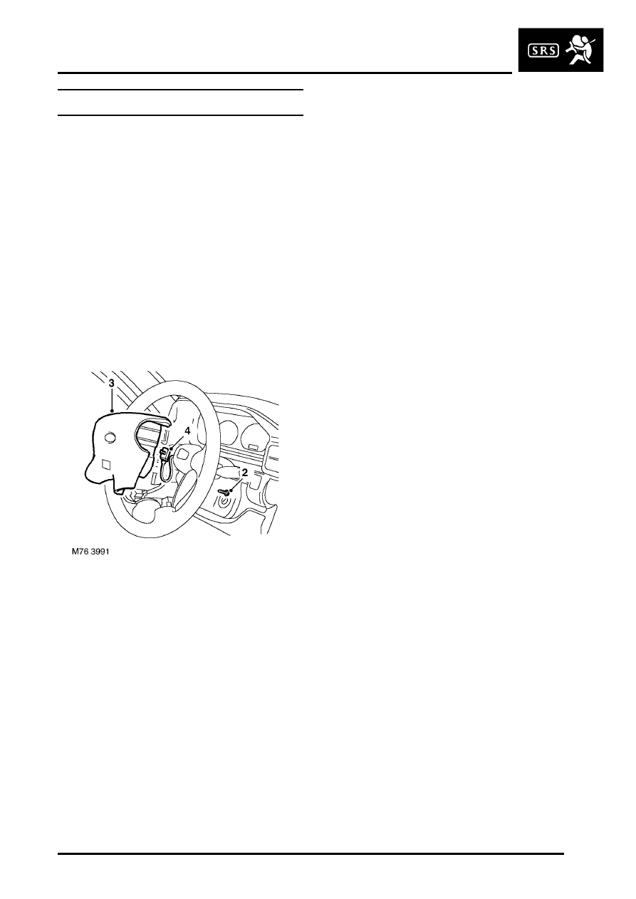
2. Remove 2 Torx bolts securing airbag module to 

steering wheel.

3. Release airbag module from steering wheel.

CAUTION: Do not allow the airbag module 
to hang by the airbag harness.

4. Disconnect SRS connector from air bag 

module.

5. Remove airbag module.

WARNING: Store the airbag module with the 
deployment side uppermost. If it is stored 
deployment side down, accidental 
deployment will propel the airbag module 
with enough force to cause serious injury.

Refit

1. Position airbag module and fit connector with 

harness pointing upwards.

NOTE: If the airbag module is to be replaced, 
the bar code of the new module must be 
recorded.

2. Fit airbag module to steering wheel and tighten 

Torx bolts to 9 Nm (7 lbf.ft).

3. Connect battery leads, earth lead last.

RESTRAINT SYSTEMS

75-12

REPAIRS

Air bag - fascia - passenger

$% 76.74.02

Remove

WARNING: It is imperative that before any 
work is undertaken on the SRS system the 
appropriate information is read thoroughly.

WARNING: When removing, testing or 
installing an airbag module, do not lean 
directly over it.

1. Make the SRS system safe. 


 + 

 GENERAL INFORMATION, 

Supplementary restraint system 
precautions.

2. Remove 2 screws securing airbag lower 

finisher.

3. Remove finisher.
4. Remove 4 Torx bolts securing airbag module to 

fascia.

5. Release airbag from fascia.

CAUTION: Do not allow the airbag module 
to hang by the airbag harness.

6. Disconnect SRS connector from air bag 

module.

7. Remove airbag module.

WARNING: Store the airbag module with the 
deployment side uppermost. If it is stored 
deployment side down, accidental 
deployment will propel the airbag module 
with enough force to cause serious injury.

Refit

NOTE: If the airbag module is to be replaced, 
the bar code of the new module must be 
recorded.

1. Position airbag and fit connector.
2. Fit airbag to fascia and tighten Torx screws to 9 

Nm (7 lbf.ft).

3. Position airbag lower finisher and tighten 

screws.

4. Connect battery leads, earth lead last.

RESTRAINT SYSTEMS

REPAIRS

75-13

Diagnostic control unit (DCU) 

$% 76.74.06

Remove

WARNING: It is imperative that before any 
work is undertaken on the SRS system the 
appropriate information is read thoroughly.

1. Make the SRS system safe. 


 + 

 GENERAL INFORMATION, 

Supplementary restraint system 
precautions.

2. Remove heater assembly.


 + 

 HEATING AND VENTILATION, 

REPAIRS, Heater unit.

3. Disconnect multiplug from DCU.
4. Remove 3 Torx bolts securing DCU to body and 

remove DCU. Discard Torx bolts.

Refit

1. Fit DCU to body and secure with new bolts. 

Tighten bolts to 9 Nm (7 lbf.ft).

2. Connect multiplug to DCU.
3. Fit heater assembly.


 + 

 HEATING AND VENTILATION, 

REPAIRS, Heater unit.

4. Connect battery leads, earth lead last.

Rotary coupler - (SRS) air bag system

$% 76.74.20

Remove

WARNING: It is imperative that before any 
work is undertaken on the SRS system the 
appropriate information is read thoroughly.

1. Make the SRS system safe. 


 + 

 GENERAL INFORMATION, 

Supplementary restraint system 
precautions.

CAUTION: Before disconnecting any part of 
the steering linkage, ensure the road wheels 
are positioned straight ahead and the 
steering wheel is prevented from turning. 
Unrestricted turning of the steering wheel 
will damage the SRS rotary coupler.

2. Remove steering wheel.


 + 

 STEERING, REPAIRS, Steering 

wheel.

CAUTION: Use adhesive tape to prevent 
rotation of the rotary coupler once the 
steering wheel is removed.

3. Remove steering column nacelle.


 + 

 STEERING, REPAIRS, Nacelle - 

column.

4. Disconnect 2 multiplugs from rotary coupler.
5. Remove 4 screws and remove rotary coupler.

CAUTION: Do not dismantle the rotary 
coupler, it has no serviceable parts and 
must be replaced as a complete assembly.

RESTRAINT SYSTEMS

75-14

REPAIRS

Refit

1. Ensure the rotary coupler is installed in its 

centred position. To obtain centre position, 
rotate coupler gently clockwise and 
anticlockwise until the white segment appears 
on the indicator wheel.

CAUTION: Ensure front road wheels are in 
the straight ahead position.

2. Fit rotary coupler and secure with screws.
3. Connect multiplugs to rotary coupler.
4. Fit steering column nacelle.


 + 

 STEERING, REPAIRS, Nacelle - 

column.

5. Fit steering wheel.


 + 

 STEERING, REPAIRS, Steering 

wheel.

6. Connect battery leads, earth lead last.

Airbag deployment tool SMD 4082/1- self 
test procedure

$% 76.74.99

Test

1. Insert BLUE and YELLOW connectors of tool 

lead into corresponding sockets on face of tool.

2. Connect crocodile clips of second tool lead to 

battery, RED to positive and BLACK to 
negative.

3. RED "READY" light should illuminate.
4. Press and hold both operating buttons.
5. GREEN "DEFECTIVE" light should illuminate.
6. Release both operating buttons.
7. RED "READY" light should illuminate. 
8. Disconnect tool from battery.
9. Disconnect blue and yellow connectors from 

tool face sockets.

10. Self test now complete. 


Content   ..  196  197  198  199   ..