Freelander 1. Manual - part 179


  Index      Land Rover     Freelander 1 - service manual 2002 year


Search            


Content   ..  177  178  179  180   ..


Freelander 1. Manual - part 179


STEERING

REPAIRS

57-21

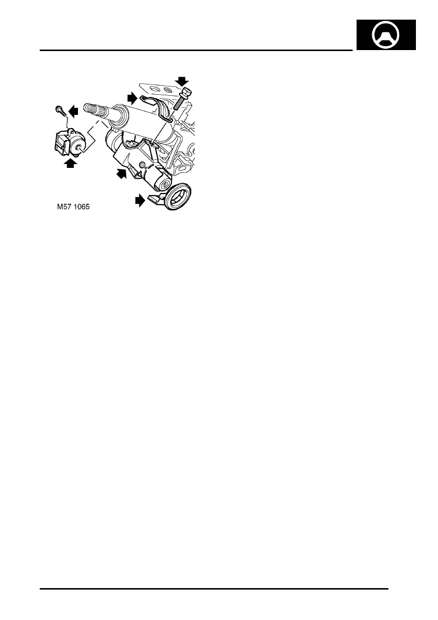
22. Remove 2 screws securing ignition switch and 

remove ignition switch.

23. Remove passive coil.
24. Position steering column assembly in a vice.
25. Centre punch or drill out steering lock shear 

bolts.

CAUTION: If steering column is to be re-
used, take care not to deform or damage 
column in vice.

26. Remove steering column lock.

CAUTION: Take care not to damage steering 
lock body if the lock is to be refitted.

Refit

1. Remove column from vice.
2. Fit new cable ties to steering column.
3. Models with automatic transmission: Fit key 

interlock cable clip.

4. Position steering column to vehicle, locate 

steering column on PAS rack, aligning column 
coupling with PAS rack input flag.

5. Locate steering column on studs fit nuts but do 

not tighten at this stage.

6. Fit bolts and snubber to pivot mountings and 

tighten bolts to 14 Nm (10 lbf.ft).

7. Tighten nuts to 14 Nm (10 lbf.ft).
8. Fit and tighten PAS rack pinion clamp bolt to 32 

Nm (24 lbf.ft).

CAUTION: Nuts and bolts must be tightened 
with weight of vehicle on suspension.

9. Models with automatic transmission: 

Remove clamp bolt from height adjuster and 
position key interlock cable.

10. Models with automatic transmission: Fit 

height adjuster clamp bolt and tighten nut to 10 
Nm (7.5 lbf.ft). Ensure bolt and plastic stop are 
correctly located in slot in column bracket. 

11. Models with automatic transmission: Fit 

height adjuster lever and tighten bolt 12 Nm (9 
lbf.ft). Ensure lever is in the fully up position 
before tightening bolt. Hold clamp bolt nut to 
prevent nut rotation.

12. Models with automatic transmission: 

Remove starter key from column lock.

13. Models with automatic transmission: Align 

key interlock cable to column lock and tighten 
union to 4 Nm (3 lbf.ft).

14. Models with automatic 

transmission:Position lock to steering column 
assembly and fit shear bolts. Do not tighten 
shear bolts at this stage.

15. Models with automatic transmission: Insert 

starter key, check operation of steering lock 
and that key turns freely.

16. Models with automatic transmission: 

Ensure correct operation of key interlock cable.

17. Models with automatic transmission: 

Remove starter key from column lock.

18. Models with automatic transmission: 

Tighten shear bolts fully and shear heads off.

19. Models with automatic transmission: Fit 

passive coil.

20. Models with automatic transmission: 

Position ignition switch to column, fit and 
tighten screws.

21. Models with automatic transmission: 

Secure key interlock cable in clip.

22. Models with automatic transmission: 

Ensure key interlock cable is correctly fitted.

23. Fit side support bolt and tighten to 10 Nm (7.5 

lbf.ft).

24. Position harness and secure cable ties.
25. Fit fusebox cover and close glove box lid.
26. Connect multiplugs to column switch and 

passive coil.

27. Fit aperture trim and secure with screws.
28.  Fit steering column multi purpose switch.


 + 

 LIGHTING, REPAIRS, Switch - 

combined direction indicator/headlight/
horn.

29. Connect battery earth lead.

STEERING

57-22

REPAIRS

Ball joint - track rod

$% 57.55.07

Remove

1. Raise front of vehicle.

WARNING: Do not work on or under a 
vehicle supported only by a jack. Always 
support the vehicle on safety stands.

2. Remove front road wheel.

3. Remove pinch bolt securing ball joint to 

turnbuckle.

4. Remove nut from ball joint and discard.
5. Fit an M12 nut to ball joint, flush with end of pin.
6. Using tool LRT-57-043, separate ball joint from 

steering arm. Remove M12 nut and release ball 
joint from steering arm.

7. Remove ball  joint, note the number of turns for 

refit.

Refit

1. Fit ball joint to turnbuckle to number of turns 

noted in remove.

2. Fit pinch bolt but do not tighten at this stage.
3. Clean ball joint taper and taper seat.

4. Fit ball joint to steering arm, fit new nut and 

tighten to 55 Nm (41 lbf.ft).

CAUTION: Ensure slots in turn buckle 
clamps are aligned.

5. Fit road wheel(s) and tighten nuts to 115 Nm 

(85 lbf.ft).

6. Remove stands and lower vehicle.
7. Check and adjust front wheel alignment. 


 + 

 STEERING, ADJUSTMENTS, Front 

wheel alignment - check & adjust.

WARNING: Ensure all track rod pinch bolts 
are tightened to the correct torque on 
completion of the front wheel alignment 
check.

STEERING

REPAIRS

57-23

Track rod

$% 57.55.09

Remove

1. Td4 & KV6 models: Remove steering rack.


 + 

 STEERING, REPAIRS, Power 

steering rack.

2. Remove Torx bolt securing track rod to PAS 

rack. Discard Torx bolt.

3. Remove track rod and spacer.

CAUTION: Note orientation of spacers 
before dismantling.

4. Hold track rod securely and loosen pinch bolt in 

track rod end.

NOTE: Do not carry out further dismantling if 
component is removed for access only.

5. Remove ball  joint, note the number of turns for 

refit.

6.  Remove pinch bolt from track rod.

7. Remove turnbuckle and note the number of 

turns for refit.

NOTE: Thread is left handed.

Refit

1. Fit turnbuckle to track rod to number of turns on 

remove.

2. Fit pinch bolt but do not tighten at this stage.
3. Fit ball joint to turnbuckle to number of turns 

noted in remove.

4. Fit pinch bolt but do not tighten at this stage.

CAUTION: Ensure slots in turn buckle 
clamps are aligned.

5. Clean spacer, support plate and track rod ball 

joint.

6. Fit spacer to rack.

CAUTION: Ensure spacers are aligned and 
fitted correctly.

7. Fit track rod to PAS rack.
8. Hold track rod parallel to PAS rack, fit new Torx 

bolt and tighten to 100 Nm (74 lbf.ft).

STEERING

57-24

REPAIRS

9. Td4 & KV6 models: Fit steering rack.


 + 

 STEERING, REPAIRS, Power 

steering rack.

10. Check and adjust front wheel alignment. 


 + 

 STEERING, ADJUSTMENTS, Front 

wheel alignment - check & adjust.

WARNING: Ensure all track rod pinch bolts 
are tightened to the correct torque on 
completion of the front wheel alignment 
check.

Steering wheel

$% 57.60.01

Remove

1. Remove airbag module from steering wheel.


 + 

 RESTRAINT SYSTEMS, REPAIRS, 

Air bag - steering wheel.

2. Disconnect multiplug from rotary coupler.
3. Centralise steering wheel with road wheels in 

straight ahead position.

4. Restrain steering wheel and loosen self locking 

nut securing steering wheel to column.

5. Pull steering wheel from column splines.
6. Remove and discard self-locking nut.
7. Remove steering wheel.


Content   ..  177  178  179  180   ..