Freelander 1. Manual - part 80


  Index      Land Rover     Freelander 1 - service manual 2002 year


Search            


Content   ..  78  79  80  81   ..


Freelander 1. Manual - part 80


ENGINE - K SERIES KV6

REPAIRS 12-3-11

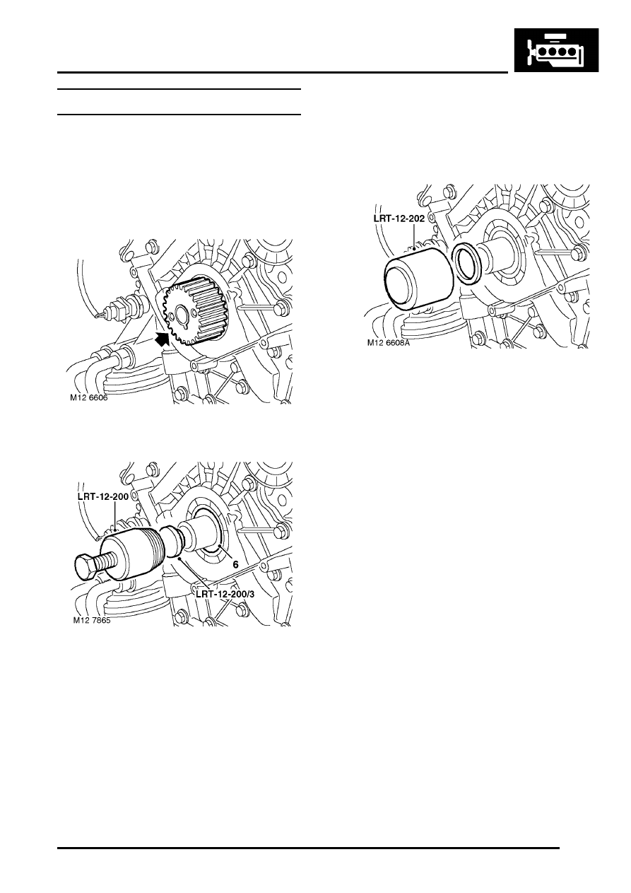
Crankshaft front oil seal

$% 12.21.14

Remove

1. Disconnect battery earth lead.
2. Remove camshaft timing belt.


 + 

 ENGINE - K SERIES KV6, REPAIRS, 

Camshaft timing belt.

3. Remove crankshaft gear.

4. Fit thrust button, LRT-12-200/3 to end of 

crankshaft.

5. Screw LRT-12-200 into crankshaft front oil 

seal.

6. Tighten centre bolt of LRT-12-200 to remove oil 

seal.

7. Remove and discard oil seal from special tool.
8. Remove thrust button from crankshaft.

Refit

1. Clean oil seal recess in oil pump and running 

surface on crankshaft, ensure bolt holes are 
clean and dry.

2. Fit oil seal guide, from seal kit, over end of 

crankshaft.

3. Position new seal on crankshaft up against oil 

pump housing. Drift seal into place using tool 
LRT-12-202. 

4. Remove LRT-12-202 and oil seal guide from 

crankshaft.

5. Fit gear to crankshaft.
6. Fit camshaft timing belt.


 + 

 ENGINE - K SERIES KV6, REPAIRS, 

Camshaft timing belt.

7. Connect battery earth lead.
8. Top-up engine oil.


 + 

 MAINTENANCE, MAINTENANCE, 

Engine Oil and Filter – KV6.

ENGINE - K SERIES KV6

12-3-12 REPAIRS

Crankshaft rear oil seal

$% 12.21.20

Remove

1. Remove torque converter drive plate.


 + 

 ENGINE - K SERIES KV6, REPAIRS, 

Torque converter drive plate.

2. Remove and discard 5 bolts securing 

crankshaft rear oil seal to cylinder block.

3. Remove and discard crankshaft rear oil seal.

Refit

1. Clean cylinder block face and oil seal running 

surface on crankshaft; ensure bolt holes are 
clean and dry.

2. Position oil seal protector, LRT-12-061 to 

crankshaft.

3. Position oil seal to crankshaft.

CAUTION: Oil seal must be fitted dry.

4. Fit new Patchlok bolts securing oil seal to 

cylinder block and using sequence shown, 
tighten to 8 Nm (6 lbf.ft).

5. Remove oil seal protector.
6. Fit torque converter drive plate.


 + 

 ENGINE - K SERIES KV6, REPAIRS, 

Torque converter drive plate.

7. Check engine oil level, top-up if necessary.


 + 

 MAINTENANCE, MAINTENANCE, 

Engine Oil and Filter – KV6.

ENGINE - K SERIES KV6

REPAIRS 12-3-13

Cylinder head gasket - LH

$% 12.29.02

Remove

1. Disconnect battery earth lead.
2. Drain cooling system.


 + 

 COOLING SYSTEM - K SERIES KV6, 

ADJUSTMENTS, Coolant - drain and refill.

3. Remove inlet manifold chamber.


 + 

 MANIFOLDS & EXHAUST SYSTEMS 

- K SERIES KV6, REPAIRS, Seals - inlet 
manifold chamber.

4. Remove LH exhaust manifold gasket.


 + 

 MANIFOLDS & EXHAUST SYSTEMS 

- K SERIES KV6, REPAIRS, Gasket - exhaust 
manifold - LH - Non NAS.
 

 + 

 MANIFOLDS & EXHAUST SYSTEMS 

- K SERIES KV6, REPAIRS, Gasket(s) - 
exhaust manifold - LH - NAS.

5. Remove camshaft timing belt.


 + 

 ENGINE - K SERIES KV6, REPAIRS, 

Camshaft timing belt.

6. Remove 4 bolts securing LH front camshaft 

timing belt cover backplate to cylinder head; 
remove backplate.

7. Remove LH camshaft cover gasket.


 + 

 ENGINE - K SERIES KV6, REPAIRS, 

Camshaft cover gasket - LH.

8. Remove 3 nuts and 3 bolts securing ignition 

coils to LH inlet manifold and release coil earth 
lead.

9. Remove ignition coils and position aside.

10. Release clip and disconnect coolant bleed 

hose from inlet manifold and move hose aside.

11. Depress locking collar and release breather 

hose from LH inlet manifold.

ENGINE - K SERIES KV6

12-3-14 REPAIRS

12. Disconnect clips securing RH injector harness 

to injector protection cover - if fitted or from 
bosses on fuel rail. 

13. Remove 2 bolts securing protection cover - if 

fitted and fuel rail to RH inlet manifold, remove 
cover.

14. Remove 2 bolts securing fuel rail to LH inlet 

manifold.

15. Release injectors from manifolds and carefully 

lay fuel rail and injectors aside.

CAUTION: Always fit plugs to open 
connections to prevent contamination.

16. Using sequence shown, progressively loosen 

and remove 8 cylinder head bolts.

17. With assistance, remove cylinder head 

assembly.

CAUTION: Support both ends of cylinder 
head on blocks of wood.

18. Remove and discard cylinder head gasket.

Do not rotate crankshaft whilst RH cylinder 
head is fitted.

19. Remove and discard 2 cylinder head locating 

dowels.

Note: Replacement dowels are supplied with 
new cylinder head gasket.


Content   ..  78  79  80  81   ..