Freelander 1. Manual - part 76


  Index      Land Rover     Freelander 1 - service manual 2002 year


Search            


Content   ..  74  75  76  77   ..


Freelander 1. Manual - part 76


ENGINE - K SERIES 1.8

OVERHAUL 12-2-77

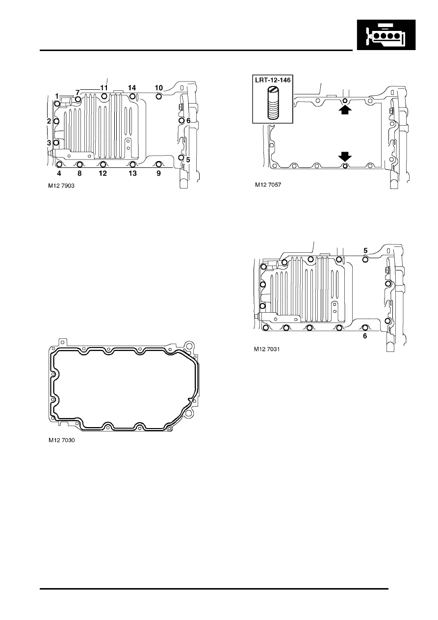
5. Noting the fitted position of 2 M8 x 60 mm bolts 

and using the sequence shown, remove 14 
bolts securing sump to bearing ladder.

6. Using a mallet, gently tap sump sideways to 

release sealant bond, remove sump.

CAUTION: Do not lever between sump and 
bearing ladder.

Refit

1. Clean inside of sump. Use a lint-free cloth and 

suitable solvent to clean mating faces of sump 
and bearing ladder.

2. Apply a continuous bead of sealant, Part 

Number STC 4600, to sump face and spread to 
an even film using a roller.

CAUTION: To avoid contamination, 
assembly should be completed immediately 
after application of sealant.

3. Fit alignment pins, LRT-12-146, to positions 

shown.

4. Position sump to bearing ladder, fit 2 bolts at 

positions 5 and 6 and tighten to 4 Nm (3 lbf.ft).

5. Fit 10 bolts into remaining holes, lightly tighten 

all bolts. Ensure that the two M8 x 60 longer 
bolts are fitted into rearmost holes in sump.

6. Fit bolts securing sump to gearbox housing, 

lightly tighten and then loosen bolts. This will 
correctly align the rear sump flange to gearbox.

7. Remove alignment pins, LRT-12-146, fit and 

lightly tighten 2 remaining bolts.

ENGINE - K SERIES 1.8

12-2-78 OVERHAUL

8. Ensure that the rear sump flange is aligned to 

gearbox housing and progressively tighten 
sump bolts in the sequence shown, M8 x 25 
bolts to 25 Nm (18 lbf.ft) and M8 x 60 bolts to 30 
Nm (22 lbf.ft).

9. Tighten bolts securing gearbox to sump to 45 

Nm (33 lbf.ft).

10. Position support bracket to IRD unit and engine 

sump, fit and tighten bolts securing support 
bracket to IRD to 50 Nm (37 lbf.ft) and bolts 
securing support bracket to engine sump to 45 
Nm (33 lbf.ft).

11. Fit and tighten upper bolt securing IRD support 

bracket to cylinder block to 45 Nm (33 lbf.ft).

Camshaft timing belt

$% 12.65.18.01

Remove

1. Using a 13 mm spanner, rotate PAS drive belt 

tensioner and insert a suitable 4 mm diameter 
pin through centre of hexagon into tensioner 
backplate. Remove PAS drive belt.

2. Loosen alternator pivot bolts and adjuster link 

bolts. Release belt tension using adjusting bolt 
and remove drive belt.

ENGINE - K SERIES 1.8

OVERHAUL 12-2-79

3. Models with A/C: Fit a 13 mm spanner to 

hexagon on ancillary drive belt tensioner and 
rotate fully clockwise to release tension on 
drive belt.

4. Models with A/C: To hold tensioner in this 

position, fit a suitable pin, not exceeding 3 mm 
in diameter, into hole in tensioner backplate. 
Remove ancillary drive belt.

5. Disconnect Lucar connector from starter 

solenoid.

6. Remove 2 bolts securing starter motor to 

gearbox and remove starter motor.

7. Remove camshaft timing belt upper cover.


 + 

 ENGINE - K SERIES 1.8, REPAIRS, 

Cover - timing gear - upper.

8. Rotate crankshaft clockwise to align camshaft 

gear timing marks.

CAUTION: Never use the camshaft gear, the 
camshaft gear retaining bolts or the timing 
belt to turn the crankshaft.

9. Fit camshaft gear alignment tool LRT-12-134.

10. Models with A/C: Hold ancillary drive belt 

tensioner, remove pin and allow tensioner to 
move fully anti-clockwise.

11. Remove camshaft timing belt lower cover.


 + 

 ENGINE - K SERIES 1.8, REPAIRS, 

Cover - timing belt - front lower - with A/C.
 

 + 

 ENGINE - K SERIES 1.8, REPAIRS, 

Cover - timing belt - front lower - without A/
C.

ENGINE - K SERIES 1.8

12-2-80 OVERHAUL

12. Remove and discard timing belt tensioner bolt.
13. Disengage index wire from its fitted position 

whilst at the same time removing timing belt 
tensioner.

14. If camshaft timing belt is to be refitted, mark 

direction of rotation on timing belt.

15. Remove camshaft timing belt.

CAUTION: Ease the timing belt off the gears 
using the fingers only, metal levers may 
damage the belt and gears. Do not rotate the 
crankshaft or camshafts with the timing belt 
removed and cylinder head fitted. Timing 
belt must be replaced if cylinder head is to 
be removed or new drive gears, tensioner or 
coolant pump are to be fitted. Timing belts 
must be stored and handled with care. 
Always store a belt on its edge with a bend 
radius greater than 50 mm (2.0 in). Do not 
use a timing belt that has been twisted or 
bent double as this will damage the 
reinforcing fibres. Do not use a timing belt if 
debris other than belt dust is found in the 
timing belt covers. Do not use a timing belt 
if partial engine seizure has occurred. Do 
not use a timing belt if mileage exceeds 
72,000 km (45,000 miles). Do not use an oil 
or coolant contaminated belt, cause of 
contamination must be rectified.

Refit

1. Clean crankshaft timing gear, camshaft timing 

gears, coolant pump drive gear and tensioner 
pulley.

CAUTION: If sintered gears have been 
subjected to prolonged oil contamination, 
they must be soaked in solvent and then 
thoroughly washed in clean solvent before 
refitting. Because of the porous 
construction of sintered material, oil 
impregnated in the gear will emerge and 
contaminate the belt.

2. Check correct alignment of camshaft timing 

marks and that tool LRT-12-134 is locking 
camshaft gears.

3. Check correct alignment of dots on crankshaft 

gear with flange on oil pump - 90

°

 BTDC.

4. Fit timing belt tensioner ensuring that index 

wire is positioned over pillar bolt and tensioner 
lever is at 9 o'clock position.


Content   ..  74  75  76  77   ..