Freelander 1. Manual - part 59


  Index      Land Rover     Freelander 1 - service manual 2002 year


Search            


Content   ..  57  58  59  60   ..


Freelander 1. Manual - part 59


ENGINE - K SERIES 1.8

REPAIRS

12-2-9

Connecting rod bearings - engine set

$% 12.17.16

Remove

1. Disconnect battery earth lead.
2. Remove cylinder head.


 + 

 ENGINE - K SERIES 1.8, REPAIRS, 

Gasket - cylinder head.

3. Remove engine sump.


 + 

 ENGINE - K SERIES 1.8, REPAIRS, 

Sump - engine reseal.

4. Temporarily remove cylinder liner clamps, 

LRT-12-144. Do not rotate crankshaft with liner 
clamps removed.

CAUTION: Ensure that cylinder head bolts 
are kept in their original fitted order.

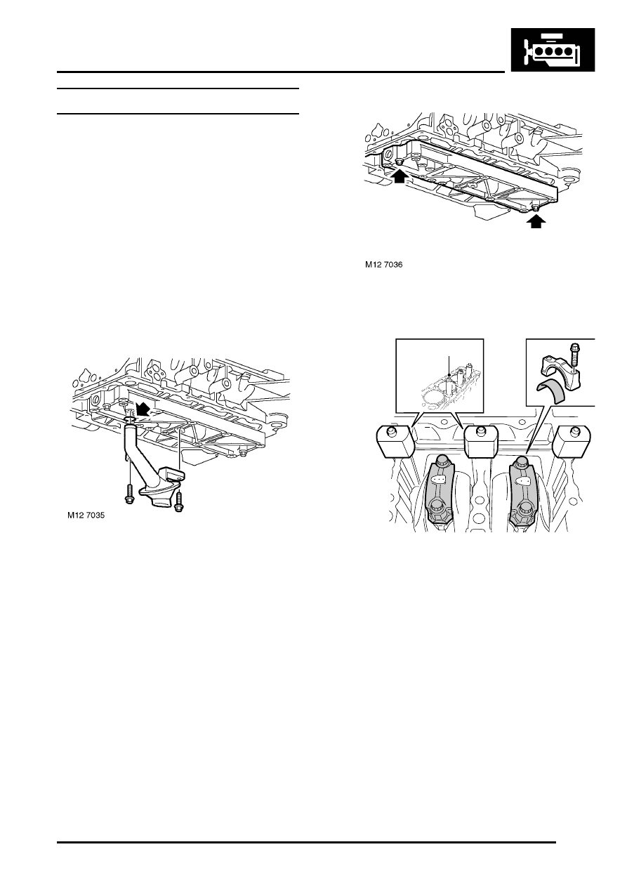
5. Remove 2 bolts securing oil pick-up strainer to 

oil rail.

6. Remove oil pick-up strainer.
7. Remove and discard 'O' ring from oil pick-up 

strainer.

8. Remove 2 nuts securing oil rail to bearing 

ladder and remove oil rail.

9. Fit cylinder liner clamps. LRT-12-144, using the 

nylon nuts supplied to retain liner clamps. 
Ensure that the feet of the liner clamps do not 
protrude over cylinder liner bores. 

10. Retain clamps using cylinder head bolts 

ensuring that bolts used are those originally 
fitted in that location. 

11. Temporarily fit crankshaft timing gear and 

pulley, fit retaining bolt and washer, lightly 
tighten bolt.

12. Rotate crankshaft clockwise and bring numbers 

2 and 3 pistons to BDC.

13. Make cylinder number reference marks on big-

end bearing caps.

14. Remove 4 dowel bolts and 2 big-end bearing 

caps from numbers 2 and 3 connecting rods, 
keep dowel bolts and bearing caps in their fitted 
order.

LRT-12-144

M12 7037

ENGINE - K SERIES 1.8

12-2-10 REPAIRS

15. Release connecting rods from crankshaft 

journals and carefully push pistons to top of 
cylinder bore. Remove and discard bearing 
shells from connecting rods and bearing caps.

16. Rotate crankshaft clockwise and bring numbers 

1 and 4 pistons to BDC.

17. Make cylinder number reference marks on big-

end bearing caps.

18. Remove 4 dowel bolts and 2 big-end bearing 

caps from numbers 1 and 4 connecting rods. 
Keep dowel bolts and bearing caps in their 
fitted order.

19. Release connecting rods from crankshaft 

journals and carefully push pistons to top of 
cylinder bore. Remove and discard bearing 
shells from connecting rods and bearing caps.

Refit

1. Using a micrometer, measure crankshaft big-

end journal diameters, taking 4 measurements 
around each journal.

2. Record big-end journal code letters from 

crankshaft rear web. Reading from left to right, 
the first letter is Number 1 big-end bearing. 
 

 + 

 GENERAL DATA, Engine – K1.8 

Petrol.

3. Record big-end bearing bore numbers. This will 

be 5, 6 or 7 located on the connecting rod 
bearing cap. Select required bearings. 
 

 + 

 GENERAL DATA, Engine – K1.8 

Petrol.

4. Colour code on edge of bearing denotes 

bearing thickness as follows: YELLOW = Thin, 
BLUE = Intermediate, RED = Thick. If two 
bearing colours are to be used, the thicker 
bearing must be fitted to the big-end bearing 
cap.

5. Clean crankshaft journals and bearing 

locations in connecting rods.

6. Select the appropriate big-end bearing shells.
7. Lubricate connecting rod journals and bearing 

shells with clean engine oil.

8. Fit bearing shells to connecting rods and caps.
9. Carefully pull connecting rods into place, fit big 

end caps noting that featherways are on 
opposite sides and lightly tighten dowel bolts. 

10. Tighten big-end bearing dowel bolts to:

l

Stage 1 - 20 Nm (15 lbf.ft)

l

Stage 2 - Further 45

°

Note: Until the cylinder head is fitted, 
crankshaft will prove difficult to rotate once big-
end bolts are tightened.

11. Using feeler gauges, check that end-float of 

each big-end bearing/connecting rod is 
between 0.10 (0.004 in) to 0.25 mm (0.010 in).

12. Clean oil rail, oil pick up and mating faces.
13. Blow out oil ways in oil rail and oil pick up.

CAUTION: A new oil rail must be fitted if a 
thread is damaged. Thread inserts (Helicoil) 
are not acceptable.

14. Temporarily remove cylinder liner clamps, 

LRT-12-144.

CAUTION:  Do not rotate crankshaft with 
liner clamps removed. Ensure that cylinder 
head bolts used to retain clamps are kept in 
their original fitted order.

M12 7040

ENGINE - K SERIES 1.8

REPAIRS 12-2-11

15. Apply continuous beads of sealant, Part 

Number STC 4600, to paths on oil rail as 
shown, then spread to an even film using a 
roller.

CAUTION: To avoid contamination, 
assembly should be completed immediately 
after application of sealant.

16. Position oil rail to bearing ladder, fit and tighten 

nuts to 9 Nm (7 lbf.ft).

17. Fit cylinder liner clamps LRT-12-144 and lightly 

tighten bolts.

CAUTION: Ensure that bolts used are those 
originally fitted in that location.

18. Lubricate new 'O' ring with clean engine oil and 

fit to pick-up strainer.

19. Position oil pick-up strainer, fit and tighten bolts 

to 12 Nm (9 lbf.ft).

20. Remove crankshaft pulley bolt, washer and 

pulley.

21. Fit engine oil sump.


 + 

 ENGINE - K SERIES 1.8, REPAIRS, 

Sump - engine reseal.

22. Fit cylinder head.


 + 

 ENGINE - K SERIES 1.8, REPAIRS, 

Gasket - cylinder head.

23. Connect battery earth lead.

Pulley - crankshaft

$% 12.21.01

Remove

1. Disconnect battery earth lead.
2. Remove ancillary drive belt.


 + 

 CHARGING AND STARTING, 

REPAIRS, Ancillary drive belt - K1.8 without 
A/C.
 

 + 

 CHARGING AND STARTING, 

REPAIRS, Ancillary drive belt - K1.8 with A/
C.

3. Remove starter motor.


 + 

 CHARGING AND STARTING, 

REPAIRS, Starter motor - K1.8.

4. Position flywheel locking tool, LRT-12-145, in 

starter motor aperture and secure with 2 bolts.

5. Remove bolt securing pulley to crankshaft and 

collect washer.

6. Remove crankshaft pulley.

ENGINE - K SERIES 1.8

12-2-12 REPAIRS

Refit

1. Clean crankshaft pulley and mating face.

2. Fit crankshaft pulley to crankshaft gear and 

ensure that the indent on pulley locates over 
the lug on crankshaft gear.

3. Fit washer and bolt securing crankshaft pulley 

and tighten to 205 Nm (151 lbf.ft).

4. Remove bolts securing flywheel locking tool, 

LRT-12-145 to starter motor aperture and 
remove locking tool.

5. Fit starter motor.


 + 

 CHARGING AND STARTING, 

REPAIRS, Starter motor - K1.8.

6. Fit ancillary drive belt.


 + 

 CHARGING AND STARTING, 

REPAIRS, Ancillary drive belt - K1.8 without 
A/C.
 

 + 

 CHARGING AND STARTING, 

REPAIRS, Ancillary drive belt - K1.8 with A/
C.

7. Connect battery earth lead.

Seal - front - crankshaft 

$% 12.21.14

Remove

1. Remove camshaft timing belt.


 + 

 ENGINE - K SERIES 1.8, REPAIRS, 

Camshaft timing belt.

2. Remove crankshaft gear.

3. Fit thrust button, tool LRT-37-010 to end of 

crankshaft.

4. Ensure bore of tool LRT-12-133 is free from 

burrs.

5. Screw tool LRT-12-133 into crankshaft front oil 

seal.

6. Tighten centre bolt of tool LRT-12-133 to 

remove oil seal.


Content   ..  57  58  59  60   ..