Discovery 2. Manual - part 745


  Index      Land Rover     Land Rover Discovery 2 - service manual 1999 year


Search            


Content   ..  743  744  745  746   ..


Discovery 2. Manual - part 745


ALARM SYSTEM AND HORN

DESCRIPTION AND OPERATION

86-4-7

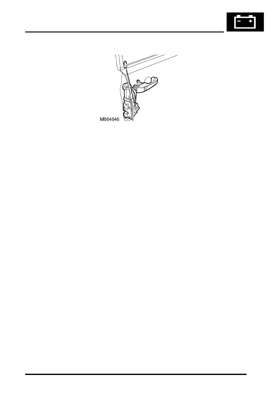
Driver's door key lock/unlock switches

The BCU uses the driver's door key lock/unlock switches to activate and deactivate the alarm system.  Two separate 
switches are incorporated into the key lock of the driver's door.

Input/Output
The input from the driver's door key lock/unlock switches to the BCU is either zero volts or an open circuit.  Zero volts 
indicates the key lock is in the lock or unlock position.  An open circuit indicates the key lock is in the centre position.  
When the BCU senses an open circuit, it pulls the input high internally.

The driver's door key lock /unlock switches have a dedicated signal input to the BCU.  This allows the BCU to identify 
the lock/unlock position.

TestBook provides the ability to monitor the real time state of the driver's door key lock/unlock switches.

ALARM SYSTEM AND HORN

86-4-8

DESCRIPTION AND OPERATION

Door lock actuators

The door lock actuators are D type latches.  The door locks allow the vehicle to be locked/unlocked  and super locked 
to prevent access to the vehicle via the interior door handles.

Input/Output
The driver's door lock actuator has a dedicated 12 volts power supply from the passenger compartment fuse box to 
energise the locking action of the door lock actuator.  The passenger and rear door lock actuators share a 12 volts 
power supply from the passenger compartment fuse box to energise the locking action of the door lock actuator.

To perform the super locking action all the door lock actuators receive a 12 volts power supply from the passenger 
compartment fuse box.

To perform the unlocking action for all the doors, a 12 volts power supply from the passenger compartment fuse box 
is supplied to the door lock actuators.

ALARM SYSTEM AND HORN

DESCRIPTION AND OPERATION

86-4-9

Bonnet switch

The BCU uses a plunger type switch to determine if the bonnet has been forcibly opened when the alarm has been 
set.  The switch is located under the bonnet on the left hand side of the vehicle when viewed from the rear.

Input/Output
When the bonnet is closed the bonnet activated alarm switch is in an open condition and the input to the BCU is more 
than 6 volts, in which case the BCU pulls the input high internally. When the bonnet is open the bonnet activated alarm 
switch is closed and the input to the BCU is less than 2 volts.

The bonnet activated alarm switch has a dedicated signal input to the BCU.  This allows the BCU to identify the 
position of the bonnet.

TestBook provides the ability to monitor the real time state of the switch. 

ALARM SYSTEM AND HORN

86-4-10 DESCRIPTION AND OPERATION

Volumetric sensors

The BCU uses volumetric sensors to detect any change in air movement within the vehicle.  There are two sensors 
located in the headlining of the vehicle.

Input/Output
The sensors require a regulated power supply of 12 volts, via the BCU. When a change in air movement is detected 
the sensors generate a 5 Hz pulse train to the BCU.

Each of the sensors have a dedicated signal input to the BCU.  Power to the sensors is supplied by the BCU.

TestBook provides the ability to monitor the real time state of the sensors. 


Content   ..  743  744  745  746   ..