Discovery 2. Manual - part 585
FRONT AXLE
DESCRIPTION AND OPERATION
54-3
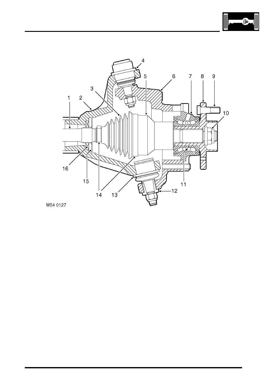
Wheel hub
Section through wheel hub
1 Drive shaft
2 Axle casing
3 Gaiter
4 Upper ball joint
5 Constant velocity joint
6 Steering knuckle
7 Hub bearing
8 Hub flange
9 Wheel stud
10 Stake nut
11 ABS sensor ring
12 Tension collet
13 Lower ball joint
14 Securing bands
15 Shield
16 Oil seal
Each wheel hub consists of a hub flange pressed into a hub bearing.
The hub flange is splined to accept the constant velocity joint of the drive shaft, which is secured to the hub flange
with a stake nut. Five studs are installed in the hub flange for the wheel nuts and a threaded hole is provided for the
brake disc securing screw.
The outer race of the hub bearing is bolted to the steering knuckle. The hub bearing is a sealed unit which contains
twin opposed roller bearings, pre-packed with grease during manufacture. A toothed ABS sensor ring is integrated
into the inner race of the hub bearing. An opening in the outer race of the hub bearing accommodates the ABS sensor.