Discovery 2. Manual - part 508


  Index      Land Rover     Land Rover Discovery 2 - service manual 1999 year


Search            


Content   ..  506  507  508  509   ..


Discovery 2. Manual - part 508


FUEL DELIVERY SYSTEM - V8

DESCRIPTION AND OPERATION

19-2-3

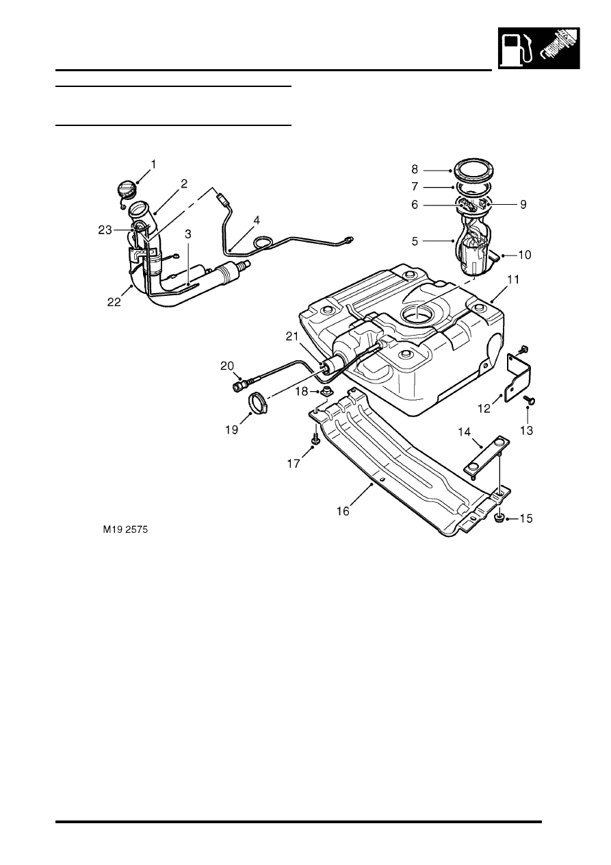
Fuel tank and breather components 
(NAS)

Fuel filler cap
Filler tube
OBD pressure sensor atmospheric pipe
Vent pipe to EVAP canister
Fuel pump, regulator and fuel gauge sender 

assembly

OBD pressure sensor (vacuum type, EVAP 

system leak detection capability only)

Seal
Locking ring
Fuel feed connection

10 Fuel gauge sender float
11 Fuel tank and breather assembly
12 Heat shield

13 Scrivet 2 off
14 Stud plate
15 Nut 2 off
16 Cradle
17 Bolt 2 off
18 Nut plate 2 off
19 Hose clip
20 LVS vent pipe
21 Tank breather connection
22 Liquid vapour separator (LVS)
23 Anti-trickle fill valve

FUEL DELIVERY SYSTEM - V8

19-2-4

DESCRIPTION AND OPERATION

Description

General
The fuel delivery system comprises a fuel tank, fuel pump and regulator and eight injectors. The system is controlled 
by the Engine Control Module (ECM) which energises the fuel pump relay and controls the operation and timing of 
each injector solenoid.
 

 + 

 ENGINE MANAGEMENT SYSTEM - V8, DESCRIPTION AND OPERATION, Description - engine 

management.

 The multiport fuel injection system is a returnless system with the fuel pressure maintained at a constant level by a 
fuel pressure regulator. The regulator is located in the fuel pump housing and returns excess fuel directly from the 
pump to the tank. 

An electrically operated fuel pump is located in the top of the fuel tank and supplies fuel at pressure to two fuel rails 
via a flexible hose. The hose is attached to the feed pipe on the fuel rail at the rear of the engine and the fuel pump 
with sealed quick release couplings.

A moulded fuel tank is located at the rear underside of the vehicle between the chassis longitudinals. The tank 
provides the attachment for the fuel pump and fuel gauge sender unit which is located inside the tank. The fuel system 
is pressurised permanently with pressurised fuel vapour venting to an EVAP canister.
 

 + 

 EMISSION CONTROL - V8, DESCRIPTION AND OPERATION, Emission Control Systems.

Fuel tank and breather
The fuel tank and breather system is a major part of the fuel delivery system. The fuel tank and breathers are located 
at the rear of the vehicle between the chassis longitudinals.

Fuel tank
The moulded fuel tank is made from High Molecular Weight (HMW) High Density Polyethylene (HDPE). Continuous 
layers of nylon additive are used during the moulding process. The nylon layers give an improved limit of fuel 
permeation through the tank wall and are also resistant to alcohol based fuels used in the NAS market.

The tank is retained in position by a metal cradle which is secured to the chassis with two nut plates and bolts at the 
rear and a stud plate and two nuts at the front. A strap above the tank is bolted to the chassis and restrains the tank 
from moving upwards. The fuel tank has a useable capacity of approximately 95 litres (25 US Gallons).

An aperture in the top surface of the tank allows for the fitment of the fuel pump, regulator and fuel gauge sender unit 
which is retained with a locking ring.

A reflective metallic covering is attached to the tank with two scrivets to shield the tank from heat generated by the 
exhaust system.

The fuel filler is located in the right hand rear quarter panel, behind an access flap. The flap is opened electrically 
using a switch on the fascia.

The filler is closed by a threaded plastic cap which screws into the filler neck. The cap has a ratchet mechanism to 
prevent over tightening and seals against the filler neck to prevent the escape of fuel vapour. The filler cap has a valve 
which relieves fuel pressure to atmosphere at approximately 0.12 to 0.13 bar (1.8 to 2.0 lbf.in

2

) and opens in the 

opposite direction at approximately 0.04 bar (0.7 lbf.in

2

) vacuum.

All markets except NAS: A moulded filler tube, made from HMW HDPE with no additional additives, connects the 
filler to the tank via a flexible rubber hose. The filler tube is connected at its top end behind the filler flap.

FUEL DELIVERY SYSTEM - V8

DESCRIPTION AND OPERATION

19-2-5

NAS markets:  A fabricated filler tube, made from stainless steel, connects the filler to the tank via a flexible rubber 
hose. The filler tube is connected at it's top end behind the filler flap.

On all vehicles that use unleaded fuel, the filler neck is fitted with an inhibitor. The inhibitor is a tapered nozzle in the 
mouth of the filler neck which will only allow the use of a standard unleaded fuel filler gun. A spring loaded flap valve 
prevents the incorrect fuel from being trickle filled from an incorrect filler gun.

Fuel tank breather system (all markets except NAS)
The filler tube incorporates a tank vent which allows air and fuel vapour displaced from the tank when filling to vent to 
atmosphere via the filler neck. A relief valve in the vent line to the EVAP canister prevents vapour escaping through 
the  canister during filling. This prevents the customer overfilling the tank and maintains the correct fuel cut-off level.

The filler tube also incorporates an integral Liquid Vapour Separator (LVS). During normal driving excess fuel vapour 
is passed via the vent line into the EVAP canister. To prevent the canister from being overloaded with fuel vapour, 
especially in hot climates, the vapour is given the opportunity to condense in the LVS. Fuel which condenses in the 
LVS flows back into the tank through the ROV's.

A breather spout within the tank controls the tank 'full' height. When fuel covers the spout it prevents fuel vapour and 
air from escaping from the tank. This causes the fuel to 'back-up' in the filler tube and shuts off the filler gun. The 
position of the spout ensures that when the filler gun shuts off, a vapour space of approximately 10% of the tanks total 
capacity remains. This vapour space ensures that Roll Over Valves (ROV's) are always above the fuel level and the 
vapour can escape and allow the tank to breathe.

The pressure relief valve fitted in the vent line to the EVAP canister prevents the customer trickle filling the tank. 
Trickle filling greatly reduces the vapour space in the tank which in turn affects the tank's ability to breathe properly, 
reducing engine performance and safety. When filling the tank, the pressures created are too low to open the pressure 
relief valve, preventing the customer from trickle filling the tank. Vapour pressures created during driving are higher 
and will open the valve allowing vapour to vent to the EVAP canister.

Four ROV's are welded onto the top surface of the tank. Each ROV is connected by a tube to the main vent line to 
the EVAP canister. The ROV's allow fuel vapour to pass through them during normal vehicle operation. In the event 
of the vehicle being overturned the valves shut-off, sealing the tank and preventing fuel from spilling from the vent line.

Fuel tank breather system (NAS)
The filler tube incorporates a tank vent which allows air and fuel vapour displaced from the tank when filling to vent to 
atmosphere via the filler neck. A filler cap operated valve within the fuel filler neck prevents vapour escaping through 
the EVAP canister during filling. This prevents the customer overfilling the tank and maintains the correct fuel cut-off 
level.

The filler tube also has an 'L' shaped, stainless steel Liquid Vapour Separator (LVS). During normal driving excess 
fuel vapour is passed via the vent line into the EVAP canister. To prevent the canister from being overloaded with fuel 
vapour, especially in hot climates, the vapour is given the opportunity to condense in the LVS. Fuel which condenses 
in the LVS flows back into the tank via the LVS vent line and through the Roll Over Valves (ROV's).

For NAS vehicles with vacuum type EVAP system leak detection capability, a small tube is located alongside the filler 
tube and terminates near to the filler neck. The tube is connected to the On Board Diagnostics (OBD) pressure sensor 
in the fuel pump and provides the sensor with a reading of atmospheric pressure to compare against the tank 
pressure
 

 + 

 EMISSION CONTROL - V8, DESCRIPTION AND OPERATION, Emission Control Systems.

A breather spout within the tank controls the tank 'full' height. When fuel covers the spout it prevents fuel vapour and 
air from escaping from the tank. This causes the fuel to 'back-up' in the filler tube and shuts off the filler gun. The 
position of the spout ensures that when the filler gun shuts off, a vapour space of approximately 10% of the tanks total 
capacity remains. This vapour space ensures that the ROV's are always above the fuel level and the vapour can 
escape to the LVS and allow the tank to breathe.

FUEL DELIVERY SYSTEM - V8

19-2-6

DESCRIPTION AND OPERATION

The filler cap operated valve closes the vent line to the EVAP canister to prevent the customer trickle filling the tank. 
Trickle filling greatly reduces the vapour space in the tank which in turn affects the tank's ability to breathe properly, 
reducing engine performance and safety. When filling the tank, the removal of the filler cap closes the valve and the 
vent line preventing the customer from trickle filling the tank. When the cap is installed the valve is opened by the cap 
allowing vapour to vent to the EVAP canister.

The four ROV's are welded inside the top surface of the tank. Each ROV is connected internally in the tank by a tube 
to the LVS. The ROV's allow fuel vapour to pass through them during normal vehicle operation. In the event of the 
vehicle being overturned the valves shut-off, sealing the tank and preventing fuel from spilling from the vent line into 
the LVS.

Fuel pump, regulator and fuel gauge sender

Electrical connector
Fuel feed pipe coupling
Pump feed pipe
Fuel regulator return pipe
Fuel gauge sender unit
Float
Gauze filter
Swirl pot
Pump electrical connections

10 Pump
11 Spring 2 off
12 OBD pressure sensor (NAS vehicles with 

vacuum type EVAP system leak detection 
capability only)

13 Fuel pressure regulator
14 'O' ring
15 'O' ring


Content   ..  506  507  508  509   ..