Discovery 2. Manual - part 498
ENGINE MANAGEMENT SYSTEM - V8
REPAIRS 18-2-71
REPAIRS
Spark plugs
$% 18.20.02
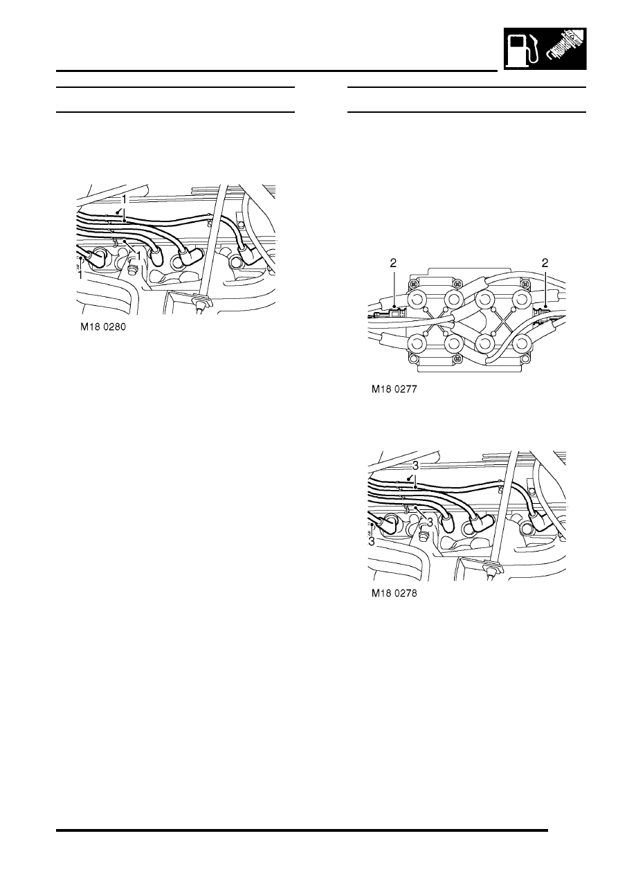
Remove
1. Noting their fitted position, disconnect ht leads
from spark plugs.
2. Using a spark plug socket, remove 8 spark
plugs.
Refit
1. Fit terminals to new spark plugs.
CAUTION: Do not attempt to adjust spark
plug gaps.
2. Fit spark plugs and tighten to 25 Nm (18 lbf.ft).
3. Connect ht leads to spark plugs ensuring they
are in the correct position.
Coil - ignition
$% 18.20.45
Remove
1. Remove upper inlet manifold assembly.
SYSTEMS - V8, REPAIRS, Gasket - inlet
manifold - upper - Without Secondary Air
Injection.
2. Disconnect multiplugs from ignition coils.
3. Release ht leads from rocker covers and
disconnect ht leads from spark plugs.
4. Carefully manoeuvre ignition coil assembly
from between engine and bulkhead.