Discovery 2. Manual - part 408


  Index      Land Rover     Land Rover Discovery 2 - service manual 1999 year


Search            


Content   ..  406  407  408  409   ..


Discovery 2. Manual - part 408


ENGINE - TD5

DESCRIPTION AND OPERATION 12-1-29
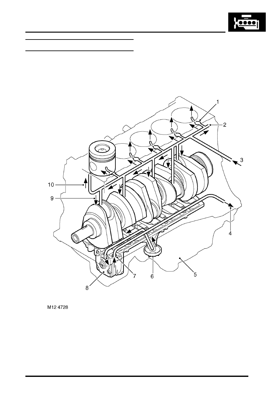
Lubrication circuit

Cylinder block flow

Oil squirt jets (5 off)
Main oil delivery gallery
Inflow from oil cooler housing
Flow to oil cooler / filters (from oil pump via 

cylinder block)

Sump
Oil pick-up pipe
Flow from oil pump (relief-valve in housing)
Oil pump

Cross-drilling supply to main and crankshaft 

bearings

10 To cylinder head

ENGINE - TD5

12-1-30 DESCRIPTION AND OPERATION

Oil from the sump is drawn up through a two-piece plastic pick-up which contains a mesh to siphon any relatively large 
pieces of material which could cause damage to the pump. The head of the pick-up is centrally immersed in the sump 
oil and oil is delivered to the inlet side of the eccentric rotor pump through a gallery in the stiffener plate.

Pressurised oil from the pump is passed through to the cylinder block where it is delivered to the centrifuge filter and 
full-flow filter via a port in the RH cylinder block which interfaces with a port in the centre gallery of the oil cooler 
housing. The oil pump contains an oil pressure relief valve which opens to allow oil to be recirculated back around the 
pump if the oil pressure increases to a high enough level.

10% of the oil flow from the pump is diverted through the centrifuge filter and returned to the sump via the centrifuge 
filter drain tube. The remaining 90% of the oil passes through the standard full-flow filter to the main oil gallery in the 
cylinder block.

ENGINE - TD5

DESCRIPTION AND OPERATION 12-1-31

Oil cooler / Filter flow (thermostat open)

To cylinder block main gallery (from rear of oil 

cooler housing)

Oil cooler housing
Oil pressure switch
Full-flow filter
Centrifuge filter

Return to sump
Flow from oil pump (via cylinder block)
Oil cooler matrix

ENGINE - TD5

12-1-32 DESCRIPTION AND OPERATION

When the engine temperature is below 74

°

 C, the thermostat in the full-flow filter housing is closed and a proportion 

of the oil flow to the main oil gallery is diverted to the oil cooler to supply an oil feed to the turbocharger bearings. Oil 
passes through the oil cooler to the front gallery in the oil cooler housing where there is a tapping to connect the feed 
pipe to the turbocharger. Oil used by the turbocharger bearings is returned to the sump through an oil drain pipe which 
connects to a port in the LH side of the cylinder block.

The remainder of the oil flow leaving the full-flow filter outlet is passed into the cylinder block via a port at the rear of 
oil cooler rear gallery. 

When the oil temperature rises above 74

°

 C the thermostat in the full-flow filter adaptor housing begins to open to 

allow a proportion of the oil from the full-flow filter to pass through the oil cooler before it reaches the main oil gallery 
in the cylinder block. In this instance, oil supply to the turbocharger bearings is fed directly from the full-flow filter 
without first passing through the oil cooler. Between 74

°

 C and 88

°

 C the thermostat valve plunger opens by about 

9mm to allow proportionally more oil to flow through the oil cooler before being passed to the cylinder block main oil 
delivery gallery. Above 88

°

C the thermostat valve continues to open by about 1mm for every 10

°

 C increase in 

temperature until the valve is fully open, when all the oil flow to the cylinder block is forced to pass to the cylinder block 
via the oil cooler.

An oil pressure switch is located in a port in the rear gallery of the oil cooler housing to sense the oil pressure level 
before flow enters the main oil gallery in the engine block. A warning lamp in the instrument cluster is switched on if 
the oil pressure is detected as being too low.
 

 + 

 INSTRUMENTS, DESCRIPTION AND OPERATION, Description.

Drillings from the cylinder block main oil gallery direct oil to the crankshaft main bearings and cross drillings in the 
crankshaft direct oil to the big-end bearings. An additional five drillings in the cylinder block supply oil at reduced 
pressure to the oil squirt jets for piston cooling and gudgeon pin lubrication.

Oil supply from the cylinder block is then passed to the cylinder head galleries through a non-return valve which is 
included as an integral item in the lower face of the cylinder head.


Content   ..  406  407  408  409   ..