Discovery 2. Manual - part 362


  Index      Land Rover     Land Rover Discovery 2 - service manual 1999 year


Search            


Content   ..  360  361  362  363   ..


Discovery 2. Manual - part 362


NAVIGATION SYSTEM

DESCRIPTION AND OPERATION

87-23

Control Switch Check Menu
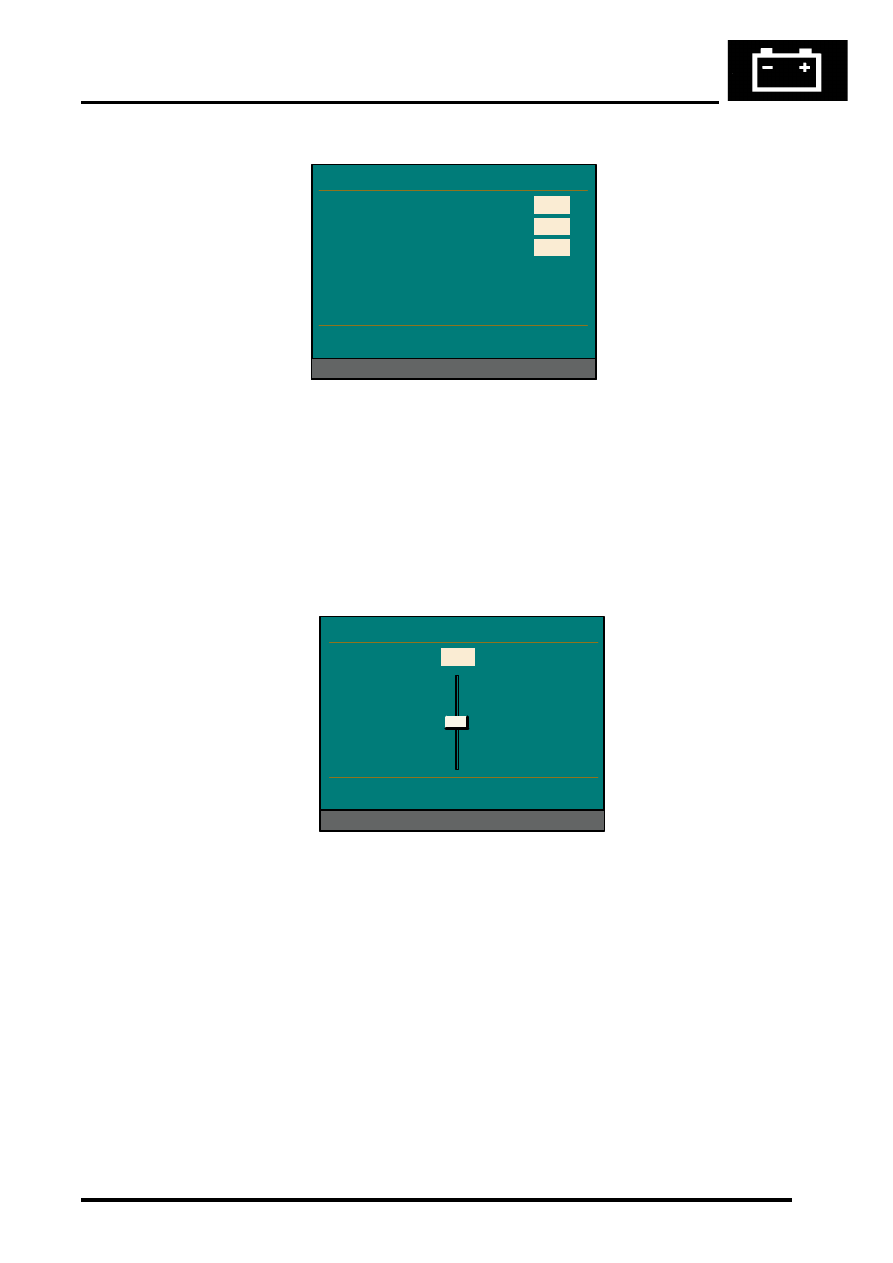
Brightness

Selecting Brightness on the display unit functions menu produces a menu with a slider bar. Turning the rotary 
controller moves the slider up and down to adjust the brightness of the LCD. Pushing the rotary controller accepts the 
new brightness setting.

Selecting <Return returns the system to the service mode menu.

Brightness Adjustment Menu

Navigation/Graphic Element
Selecting NAVIGATION / GRAPHIC ELEMENT on the service mode menu displays the version information menu for 
the navigation computer. The version information menu for the navigation computer displays the same information as 
the version information menu for the display unit, i.e. the software, hardware and diagnostic levels together with the 
bus and encoding indices, and the supplier code.

Selecting <Return returns the system to the service mode menu.

Video Module
This component is not applicable to the Discovery II system.

M86 6068

On Board Monitor Key Funct

KEY

OBM increment sensor

Radio Increment sensor

< Return

FF

00

00

Functions

M86 6069

On Board Monitor Brightness

< Return


Slider

Functions

0

NAVIGATION SYSTEM

87-24

DESCRIPTION AND OPERATION

GPS
Selecting GPS from the service mode menu displays the version information menu for the GPS receiver integrated 
into the navigation computer.

Selecting <Return returns the system to the service mode menu. Selecting Function brings up a functions menu for 
the GPS. From the functions menu, the GPS status and tracking information can be checked.

GPS Version Menu

GPS Function Menu

GPS Status Check

Selecting GPS Status on the GPS functions menu displays the status menu of the GPS system. The status menu 
shows the current position in latitude and longitude, the approximate altitude and the time and date (always displayed 
in Greenwich Mean Time (GMT)).

The ground speed and heading can be checked when the vehicle is in motion. The indicated ground speed should be 
the actual vehicle speed in m/s and the heading should be the actual direction of travel in degrees.

M86 6070

GPS Version

Receiver Version

Receiver SW Date

< Return

7.52

Functions

23.5.97

M86 6071

GPS Version

Receiver Version

Receiver SW Date

< Return

Functions

< Return

GPS Version

GPS Status

GPS Tracking Info

NAVIGATION SYSTEM

DESCRIPTION AND OPERATION

87-25

The Rec Stat/Pos Src element is used to check that the GPS system is functioning correctly. The Rec Stat window 
displays one of the following:

l

POS – The system has a current position fix. This indicates that the GPS system is working normally. The Pos 
Src
 window indicates the type of position fix (2D or 3D) and the number of satellites being received.

l

TRACK – The system is tracking a number of satellites. This indicates that the system is working normally but 
does not yet have enough information to determine the position of the vehicle. Check that there is nothing 
obstructing the GPS antenna's 'view' of the sky.

NOTE: When exposed to satellites for the first time, the GPS system can take up to 15 minutes to determine the 

position of the vehicle.

l

COMERR – There is a communication error between the GPS receiver and the navigation computer

l

SEARCH – The system is searching for satellites. If this is displayed it may mean there is a failure in the GPS 
system. First check that there is nothing obstructing the GPS antenna's 'view' of the sky. Check the connections 
between the GPS antenna and the navigation computer.

GPS Status Menu

GPS Tracking Information

Selecting the GPS Tracking Information from the GPS functions menu displays the satellite being received on each 
channel together with a signal level. The menu also displays the number of satellites that are currently being received 
and the Almanac status.

M86 6072

GPS Status

Latitude

Longitude

Altitude

Date / Time (UTC)

G Speed Heading
Rec Stat / Pos Src
PDOP / HDOP / VDOP

< Return

200 m

22.03.98

12:08

0.0 m/s

000

POS

3D/6

52  11' 26'' N

361  28' 52'' W

2.2

1.6

2.7

Functions

NAVIGATION SYSTEM

87-26

DESCRIPTION AND OPERATION

GPS Tracking Menu

Sensor Check
Selecting Sensor Test from the service mode menu causes the sensor check menu to be displayed. The sensor 
check menu is used to confirm that all the input sensors are working. Some of the tests below involve driving the 
vehicle for short distances. Before starting these tests ensure that an appropriate location, away from public roads 
and obstructions, is chosen. The system-input sensors can be tested as follows:

l

Wheel Sensors - When the vehicle is stationary the values in the wheel sensor boxes should both be zero. Drive 
the vehicle for a short distance. While driving, a number should be displayed in the left wheel sensor box. The 
value in the box should be proportional to the speed of the vehicle, and increase as the speed increases.

l

GPS Satellites – Indicates the number of satellites being received

l

GPS Status – Indicates the status of the GPS system by displaying one of the following messages:

l

Position Known – The system has a current position fix. This indicates that the GPS system is functioning 
normally.

l

Satellite Contact – The system is tracking a number of satellites. This indicates that the system is working 
correctly but does not have enough information to determine the position of the vehicle. Check that there is 
nothing obstructing GPS antenna's 'view' of the sky. It may take several minutes for the GPS system to 
acquire enough satellites to determine the vehicle's position (Position Known).

l

Satellite Search – The system is searching for satellites. If this is displayed it may mean that there is a failure 
in the GPS system. First check that the GPS antenna's 'view' of the sky is not blocked in any way. Check 
harness connections between the navigation computer and the GPS antenna.

l

GPS Error – There is a communication error between the GPS receiver and the navigation computer.

l

GYRO – Drive the vehicle forwards, in a straight line and making left and right turns. When the vehicle is moving 
in a straight line the direction arrow should be pointing to the top of the screen and the gyro value beside the 
direction arrow should remain relatively constant. When the vehicle turns to the right, the direction arrow should 
turn clockwise and the gyro value should increase. The size of the angle through which the direction icon turns 
depends on the tightness of the turn. When the vehicle turns to the left, the direction arrow should turn anti-
clockwise and the gyro value should decrease.

l

Direction of Travel – When the gear lever is in any position other than reverse, the display should show 
Forwards. When reverse is selected, the display should change to Backwards.

Selecting <Return returns the system to the service mode menu.

M86 6073

GPS Tracking Info

1
2

3

4

Visible Satellites
Almanac

< Return

08

Yes

Functions

5.3

21

7.4

05

5.9

13

12.3

04

CH

PRN

S/N

CH

PRN

S/N

4.3

27

3.9

19

18.2

02

14.3

10

5
6

7

8


Content   ..  360  361  362  363   ..