Discovery 2. Manual - part 181


  Index      Land Rover     Land Rover Discovery 2 - service manual 1999 year


Search            


Content   ..  179  180  181  182   ..


Discovery 2. Manual - part 181


FRONT SUSPENSION

DESCRIPTION AND OPERATION

60-7

DESCRIPTION AND OPERATION

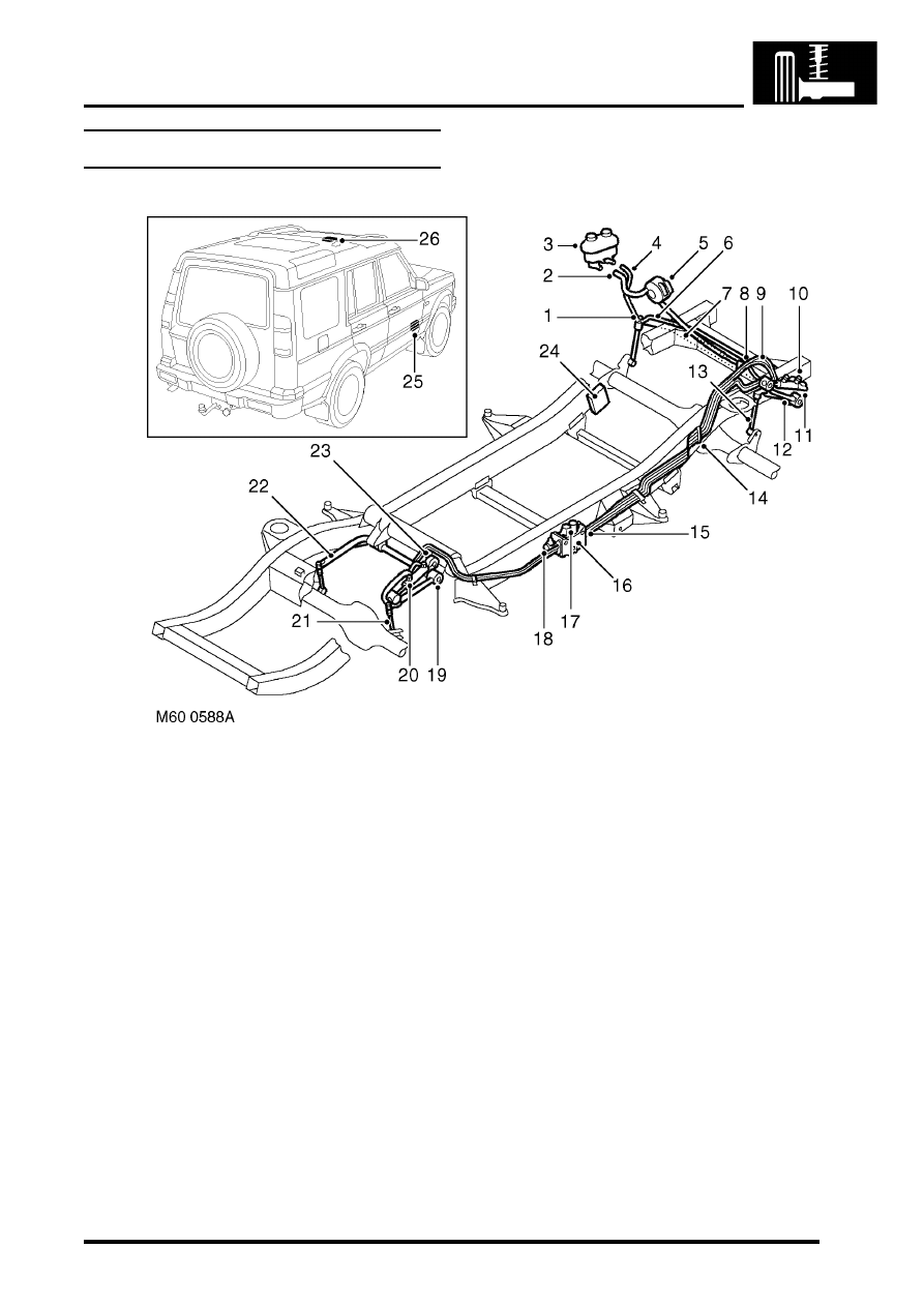
ACE system component layout

Anti-roll bar link
Suction hose
ACE/PAS reservoir
Return pipe
ACE pump
Pressure pipe
Torsion bar - front
Actuator hose
Actuator hose

10 Actuator
11 Short arm
12 Long arm
13 Anti-roll bar link

14 Isolator and bracket (2 and 4 way) 7 off
15 Pressure transducer
16 Valve block
17 Directional control valve 2 off
18 Pressure control valve
19 Long arm
20 Actuator
21 Anti-roll bar link
22 Torsion bar - rear
23 Short arm
24 ACE ECU
25 Accelerometer - lower
26 Accelerometer - upper

FRONT SUSPENSION

60-8

DESCRIPTION AND OPERATION

ACE system control diagram

Upper accelerometer
Lower accelerometer
Pressure transducer
Directional control valve
Pressure control valve
Instrument pack warning lamp
Diagnostic socket

Reverse lamp switch

10 SLABS ECU
11 Engine Control Module (ECM)
12 Ignition feed
13 ACE relay
14 Battery supply
15 ACE ECU

M60 0589B

1

2

5

4

3

6

7

8

9

10

11

12

13

14

15

FRONT SUSPENSION

DESCRIPTION AND OPERATION

60-9

Description - ACE

General
The Active Cornering Enhancement (ACE) system is used to control vehicle roll angles. The following illustrations 
show the difference in body roll angle between a conventional 'passive' anti-roll bar and the ACE system. 

Conventional 'passive' anti-roll bar

Direction of travel - Right hand bend

Body roll

Axle roll

Tyre squash

Coil springs

Body roll angle

Axle roll angle

FRONT SUSPENSION

60-10

DESCRIPTION AND OPERATION

ACE system

Direction of travel - Right hand bend

Body roll

Axle roll

Tyre squash

Torsion/Anti-roll bar

Direction of torsion/anti-roll bar twist

Coil springs
Body roll angle

Axle roll angle
Reduced body roll angle with ACE system

The system is electrically and hydraulically operated with all operations controlled by an ACE ECU located behind the 
glovebox in the passenger side footwell. The ACE system comprises front and rear torsion bars and actuators, two 
accelerometers, ECU, hydraulic pump, valve block and a fluid reservoir.

The ACE system gives improved vehicle handling and suspension characteristics and is active for both on and off-
road driving. This is achieved by hydraulic actuators applying torque to the front and rear torsion bars in response to 
lateral forces sensed by accelerometers. The ACE system prevents body roll with cornering forces of up to 0.4 g. From 
0.4 g there is a progressive increase in body roll but significantly lower than a passive system. A passive system will 
have a progressive increase in roll angle as soon as cornering forces are applied and will have a higher roll angle than 
the ACE system for the same cornering force.

The ACE system can also detect if the vehicle is driven off-road. If off-road conditions are detected the ACE system 
operation will be reduced or completely disabled at a speed of 25 mph (40 km/h) or less.

Lateral acceleration of the body is sensed by two accelerometers and signals are transmitted to the ECU. The engine 
driven hydraulic pump supplies a constant hydraulic flow to the valve block. Two directional control valves are 
solenoid operated by the ECU and these supply fluid to the applicable side of each actuator to apply an equal and 
opposite force to the torsion bar. In operation the ACE system maintains the attitude of the vehicle body when 
cornering.


Content   ..  179  180  181  182   ..