Discovery 2. Manual - part 168
STEERING
DESCRIPTION AND OPERATION
57-7
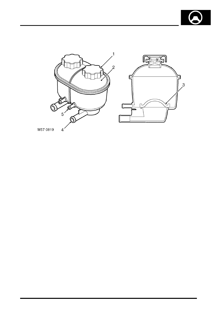
Reservoir
1 Filler cap
2 Reservoir body (dual PAS/ACE shown )
3 Filter
4 Supply connection
5 Return connection
The fluid reservoir is made of moulded plastic and is located on LH side of the engine compartment, on a bracket
which is attached to the inner wing. Dependent on the vehicles specification the reservoir may be a dual PAS/ACE,
or PAS only reservoir. Both types of reservoir are similar to each other the dual PAS/ACE reservoir has two chambers,
the PAS only reservoir has one chamber of a larger capacity. On both types of reservoir the PAS chamber has its own
filler cap and is identified by lettering on the reservoir body.
A filter of fine polyester mesh is moulded into the base of the chamber. The filter removes particulate matter from the
fluid before it is drawn into the supply connection and is non-serviceable. Upper and lower level marks are moulded
into the reservoir body, the reservoir is fitted with filler cap, a seal in the cap prevents leakage. The filler cap is pushed
onto a latch and turned through 90
°
to lock. A breather hole is incorporated in the cap to allow venting of air due to
fluid level changes during operation. The breather hole also allows air that may be in the fluid to separate out and vent
to atmosphere.
The reservoir holds hydraulic fluid and allows for expansion and contraction of the fluid due to temperature variations.
With the reservoir correctly filled the inlet to the PAS pump will be kept covered at normal operational attitudes. The
fluid flowing to the reservoir is cooled by convection from the pipe surfaces, the fluid held in the reservoir also allows
convection from the sides of the reservoir to take place. The total capacity of the reservoir with PAS only is 1000 cc
(0.264 US gallons), for vehicles fitted with PAS and ACE the total capacity of the reservoir is 500 cc (0.132 US
gallons).