Discovery 2. Manual - part 163


  Index      Land Rover     Land Rover Discovery 2 - service manual 1999 year


Search            


Content   ..  161  162  163  164   ..


Discovery 2. Manual - part 163


FRONT AXLE

DESCRIPTION AND OPERATION

54-1

FRONT AXLE

DESCRIPTION AND OPERATION

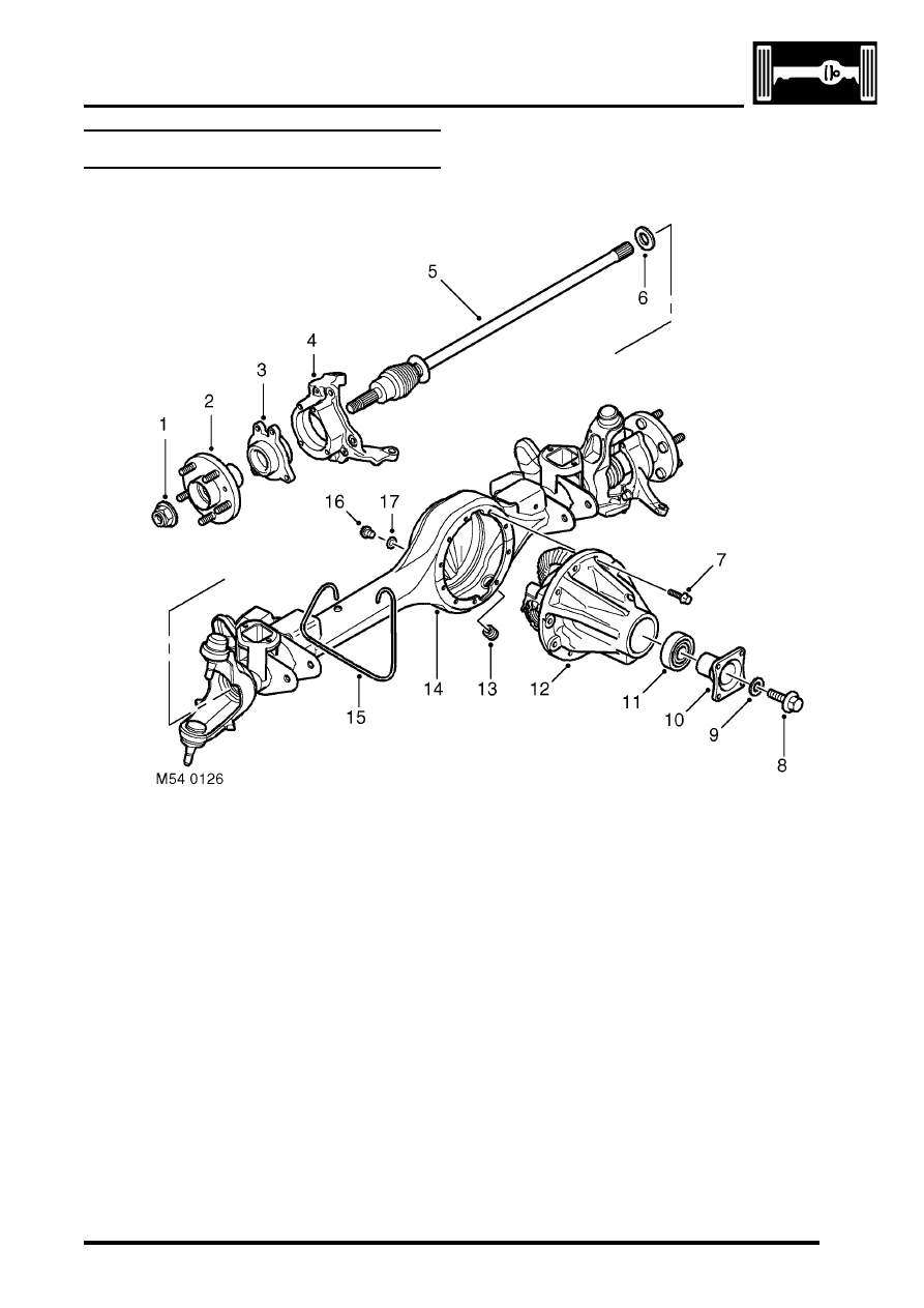
Front axle component layout

Stake nut
Hub flange
Hub bearing
Steering knuckle
Drive shaft
Oil seal
Bolt
Bolt
Washer

10 Drive flange
11 Oil seal
12 Differential unit
13 Drain plug
14 Axle casing
15 Breather tube
16 Oil level plug
17 'O' ring

FRONT AXLE

54-2

DESCRIPTION AND OPERATION

Description

General
The front axle consists of an axle casing with a differential unit attached to the right of the vehicle centre line. A wheel 
hub is installed in a steering knuckle at each end of the axle casing and connected to the differential unit by a drive 
shaft.

Axle casing
The axle casing is of welded construction, with brackets on the casing exterior for attachment to the front suspension. 
Yokes at each end of the casing incorporate upper and lower ball joints for attachment of the steering knuckles.

A differential cover on the front of the axle casing contains an oil level plug for checking and replenishment of the 
differential lubricating oil. A magnetic drain plug is installed on the underside of the casing. An oil seal is installed in 
each end of the axle casing to prevent leakage past the drive shafts.

The interior of the axle casing is ventilated through a breather tube inserted in a red plastic sleeve in the top of the 
casing. The open end of the breather tube is located in the left rear corner of the engine compartment.

Differential unit
The differential unit is of the spiral bevel type, lubricated by splash oil. The unit consists of a differential carrier 
attached to a pinion housing. In the pinion housing, the pinion is splined to a drive flange which is secured with a bolt 
and washer. An oil seal prevents leakage past the drive flange.

Steering knuckle
The steering knuckles are mounted on upper and lower ball joints in the yokes at the end of the axle casing. A tension 
collet, in the lower mounting point of each steering knuckle, accommodates manufacturing tolerances to enable the 
correct tightening of both ball joints. Lugs are incorporated on the steering knuckles for attachment of the steering 
system drag link and track rod.

FRONT AXLE

DESCRIPTION AND OPERATION

54-3

Wheel hub

Section through wheel hub

Drive shaft
Axle casing
Gaiter
Upper ball joint
Constant velocity joint
Steering knuckle
Hub bearing
Hub flange

Wheel stud

10 Stake nut
11 ABS sensor ring
12 Tension collet
13 Lower ball joint
14 Securing bands
15 Shield
16 Oil seal

Each wheel hub consists of a hub flange pressed into a hub bearing.

The hub flange is splined to accept the constant velocity joint of the drive shaft, which is secured to the hub flange 
with a stake nut. Five studs are installed in the hub flange for the wheel nuts and a threaded hole is provided for the 
brake disc securing screw.

The outer race of the hub bearing is bolted to the steering knuckle. The hub bearing is a sealed unit which contains 
twin opposed roller bearings, pre-packed with grease during manufacture. A toothed ABS sensor ring is integrated 
into the inner race of the hub bearing. An opening in the outer race of the hub bearing accommodates the ABS sensor.

Drive shaft
Each drive shaft consists of a solid rod, splined at both ends, with a constant velocity joint installed on the outboard 
end. A shield is incorporated onto each rod to protect the oil seals in the axle casing. The constant velocity joint is of 
the ball and socket type. A shaft on the constant velocity joint is splined to the hub flange. The constant velocity joint 
is pre-packed with grease and protected by a gaiter. Two securing bands retain the gaiter in position.


Content   ..  161  162  163  164   ..