Discovery 2. Manual - part 144
AUTOMATIC GEARBOX - ZF4HP22 - 24
DESCRIPTION AND OPERATION
44-7
The gearbox consists of a torque converter housing, an intermediate plate, a gearbox housing and a rear extension
housing, bolted together in series. The rear of the gearbox is supported by a rubber mounting installed between a
mounting bracket on the gearbox and the LH chassis rail. A heat shield is installed on the mounting to protect it from
the exhaust.
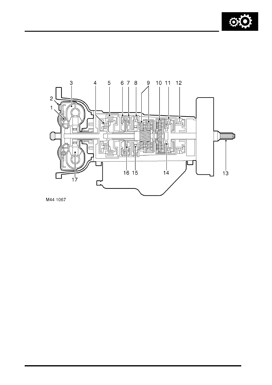
Sectioned view of gearbox
1 Lock-up clutch
2 Impeller
3 Turbine
4 Forward drive clutch
5 Reverse drive clutch
6 Brake clutch
7 Brake clutch
8 Brake clutch
9 Epicyclic gear set
10 Epicyclic gear set
11 Clutch
12 Brake clutch
13 Output shaft
14 Freewheel (one way clutch)
15 Freewheel (one way clutch)
16 Freewheel (one way clutch)
17 Stator and one way clutch
Torque converter housing
The torque converter housing attaches the gearbox to the engine and contains the torque converter. Different torque
converter housings are used to accommodate the difference between the V8 and Td5 engine interfaces. The torque
converter is connected to the engine drive plate and transmits the drive from the engine to the gearbox input shaft.
When engaged, a hydraulic lock-up clutch in the torque converter prevents slippage, to give a direct drive from the
engine to the gearbox for improved driving response.
Intermediate plate
The intermediate plate supports the gearbox input shaft and provides the interface between the transmission fluid
pump and the lubrication circuit. The pump attaches to the front of the intermediate plate and is driven by the impeller
in the torque converter. The pump pressurises transmission fluid drawn from the sump on the gearbox housing. The
pressurised fluid then circulates through the torque converter and gearbox housing components for cooling,
lubrication and gear shift purposes. Ports around the outer periphery of the intermediate plate provide the inlet and
outlet connections to the fluid cooler and a pressure take-off point for servicing.