Discovery 2. Manual - part 63


  Index      Land Rover     Land Rover Discovery 2 - service manual 1999 year


Search            


Content   ..  61  62  63  64   ..


Discovery 2. Manual - part 63


EMISSION CONTROL - V8

DESCRIPTION AND OPERATION 17-2-47

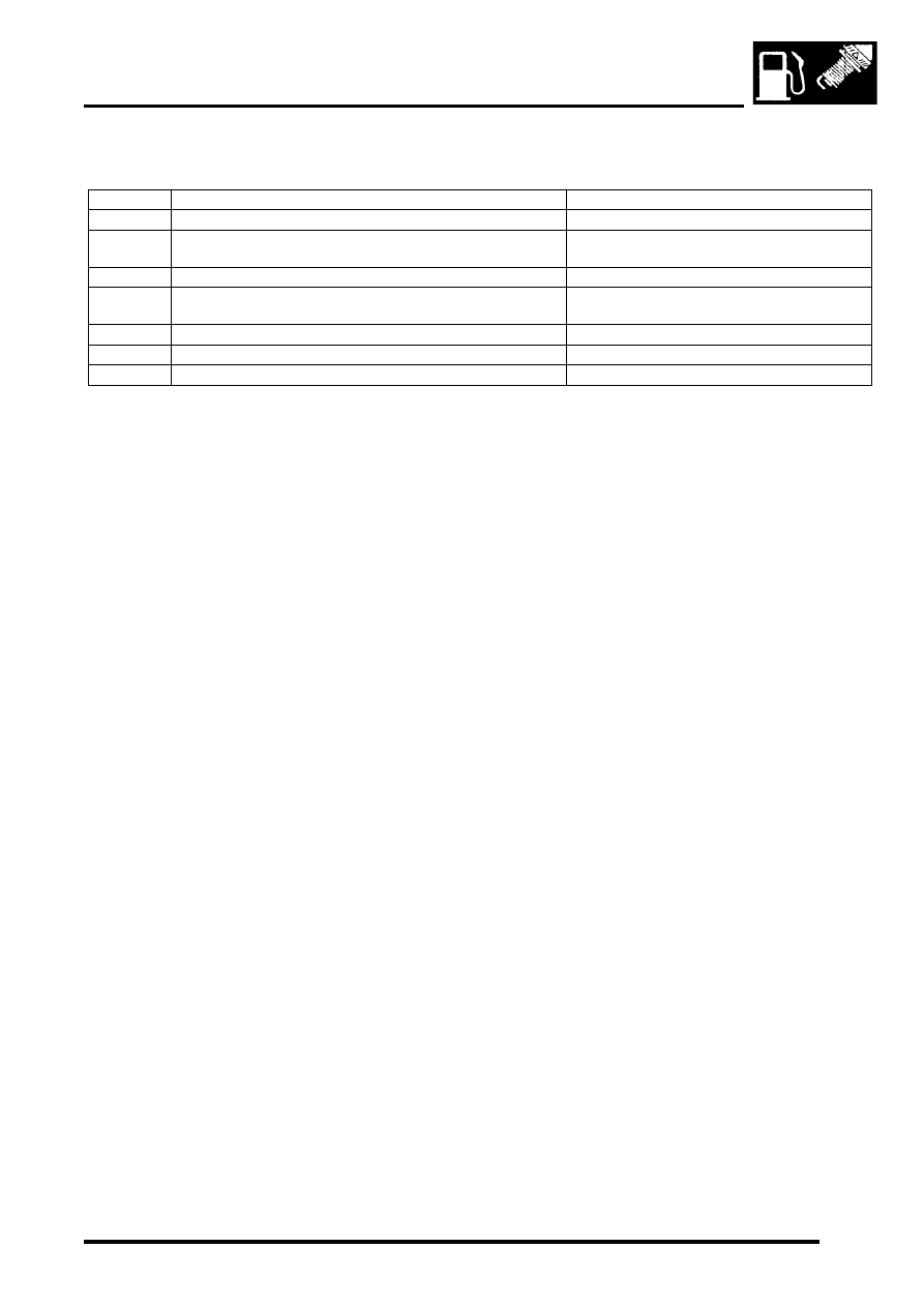
The following table shows the components itemised on the above illustration and the test applicable to each 
component.

Test 1– Secondary Air Injection (SAI) Pump
Power Supply and Relay

Check all wiring and connections.

Functional Check of SAI Pump

The ECM checks the engine coolant temperature when the engine is started in addition to checking the elapsed time 
since the last engine start. The engine coolant temperature must be below 55

°

C (131

°

F) and the ambient temperature 

above 8

°

C (46

°

F) for the SAI pump to run. Also, depending on the long term 'modelled' ambient temperature 

determined by the ECM, the minimum time elapsed required since the last engine start can be up to 8.25 hours. The 
period of time that the SAI pump runs for depends on the starting temperature of the engine and varies from 
approximately 95 seconds for a start at  8

°

C (46

°

F) to 30 seconds for a start at 55

°

C (131

°

F).

With a warm engine which is switched off and the SAI pump relay removed, the SAI pump can be supplied with power 
by bridging terminals 87 and 30 at the relay socket.

CAUTION: Ensure that terminals 87 and 87a are not connected or bridged in any way, a short circuit will 
occur.

NOTE: TestBook/T4 can also be used to force the SAI system to perform an SAI active diagnostic routine. During this 
routine the SAI pump will run for approximately 10 seconds.

When the terminals are bridged or the diagnostic routine initiated, the pump must run when requested which will be 
noticeable by the running noise of the pump. Only allow the SAI pump to run for a maximum of 90 seconds and allow 
sufficient time for the pump to cool down before running again.

If the SAI pump does not run or makes a scraping noise, it must be replaced. In this case, all other system components 
must also be checked.

Noise Complaints

If the SAI pump runs but the operating noise is excessively loud, the external components of the pump, cable, hose 
line, and decoupling segments, must be checked. Check the decoupling segments and hose line for distortion and 
the cable and hose line for contact with the pump body.

If excessive noise still occurs, the SAI pump must be replaced.

NOTE: Before a new SAI pump is fitted, the SAI control valves must checked for correct function and tightness – Refer 
to Test 2 – Secondary Air Injection (SAI) Control Valves.

When fitting a new SAI pump, ensure that the hose lines, the cable and the decoupling segments are fitted without 
tension and contact with the pump body.

Item No.

Component Description

Applicable Test

1

SAI Pump

Test 1 – Secondary Air Injection (SAI) Pump

2

SAI control valves (1 per engine bank)

Test 2 – Secondary Air Injection (SAI) Control 

Valves

3

Vacuum solenoid valve

Test 3 – Vacuum Solenoid Valve

4

Delivery hoses to SAI control valves

Test 4 – Delivery Hoses to Secondary air 

Injection (SAI) Control Valves

5

Connection to air manifold (SAI rail)

Test 5 – Connection to Air Manifold

6

Vacuum line (intake manifold to vacuum solenoid valve)

Test 6 – Vacuum Lines

7

Vacuum lines (vacuum solenoid valve to SAI control valves)

Test 6 – Vacuum Lines

EMISSION CONTROL - V8

17-2-48 DESCRIPTION AND OPERATION

Test 2 – Secondary Air Injection (SAI) Control Valves

SAI control valve
Pressure connection
Outlet

Inlet connection stopper
Hand pressure pump
Hand vacuum pump

Visually inspect the SAI control valve for external damage.

Leak Test

Remove the line from the inlet connection and connect the hand pressure pump (5) using the inlet connection stopper 
(4). Using the hand pressure pump, pressurise the SAI control valve with 100 mBar (1.45 lbf/in

2

) pressure. Maximum 

permissable pressure drop at the hand pressure pump gauge 10 mbar/minute (0.145 lbf/in

2

/minute) with the outlet (3) 

open.

Valve Opening Test

Connect the hand vacuum pump (6) to the control pressure connection (2). Depressurise the pressure connection 
using the hand vacuum pump. When the vacuum reaches -300 mbar (-4.35 lbf/in

2

), the SAI control valve (1) must 

open and the pressure on the hand pressure pump (5) gauge should drop suddenly.

Tightness of Diaphragms

The available pressure difference (vacuum) at the control pressure connection (2) must not drop over a period of time 
(Refer to Valve Opening Test).

NOTE: In the case of a leaking or incorrectly controlled SAI control valve, the inlet connection is usually heavily fouled 
and a condensate smell is noticeable on the hose line to the SAI pump.

If, after switching off the SAI pump, pulsation noise is still noticeable at the SAI pump, the SAI control valve and 
delivery hoses must be replaced before fitting a new SAI pump.

M17 0376

3

6

5

1

4

2

EMISSION CONTROL - V8

DESCRIPTION AND OPERATION 17-2-49

Test 3 – Vacuum Solenoid Valve
Function

The vacuum solenoid valve is energised for the duration of the secondary air injection. The valve is open when 
energised, the intake manifold vacuum acts on the diaphragm of the SAI control valve and the control valve opens. 
The solenoid valve is closed when de-energised.

Power Supply

Remove the harness connector from the vacuum solenoid valve and check the voltage between the connection 
terminals. No voltage must be present at the connector after switching off the SAI pump.

Opening/Tightness

Disconnect the vacuum line at one of the SAI control valves and connect a hand vacuum pump to the line. With the 
engine running at idle, a pressure difference of a minimum of 390 mbar (5.65 lbf/in

2

) must measurable on the hand 

vacuum pump gauge with the vacuum solenoid valve energised.

The vacuum solenoid valve must be sealed when de-energised. If the Opening/tightness test fails, replace the 
vacuum solenoid valv.

Test 4 – Delivery Hoses to Secondary air Injection (SAI) Control Valves
Visually inspect the delivery hoses to the SAI control valves for damage or blockage. If damage, condensate or 
deposits are found the delivery hoses must be replaced. Check the hoses for correct connection and leaks.

Test 5 – Connection to Air Manifold
Check the connection for leaks visually or by using a leak detection spray. Reseal the connection if necessary.

Test 6 – Vacuum Lines
Visually inspect the vacuum lines for damage. Check each line for leaks or blockages using the vacuum hand pump. 
Check the lines for correct connection.


Content   ..  61  62  63  64   ..