Discovery 2. Manual - part 44
 

  Index      Land Rover     Land Rover Discovery 2 - service manual 1999 year


Search            


Content   ..  42  43  44  45   ..


Discovery 2. Manual - part 44


ENGINE - V8

OVERHAUL 12-2-49

Seal - crankshaft - rear - automatic 
models

$% 12.21.20.01 

Disassembly

1. Remove CKP sensor.


 + 

 ENGINE MANAGEMENT SYSTEM - 

V8, REPAIRS, Sensor - crankshaft position 
(CKP).
 

Note: Later engines are fitted with a modified 
starter ring gear which incorporates the reluctor 
plate, spacer and hub. The modified ring gear 
may be fitted as a replacement to early 
engines.

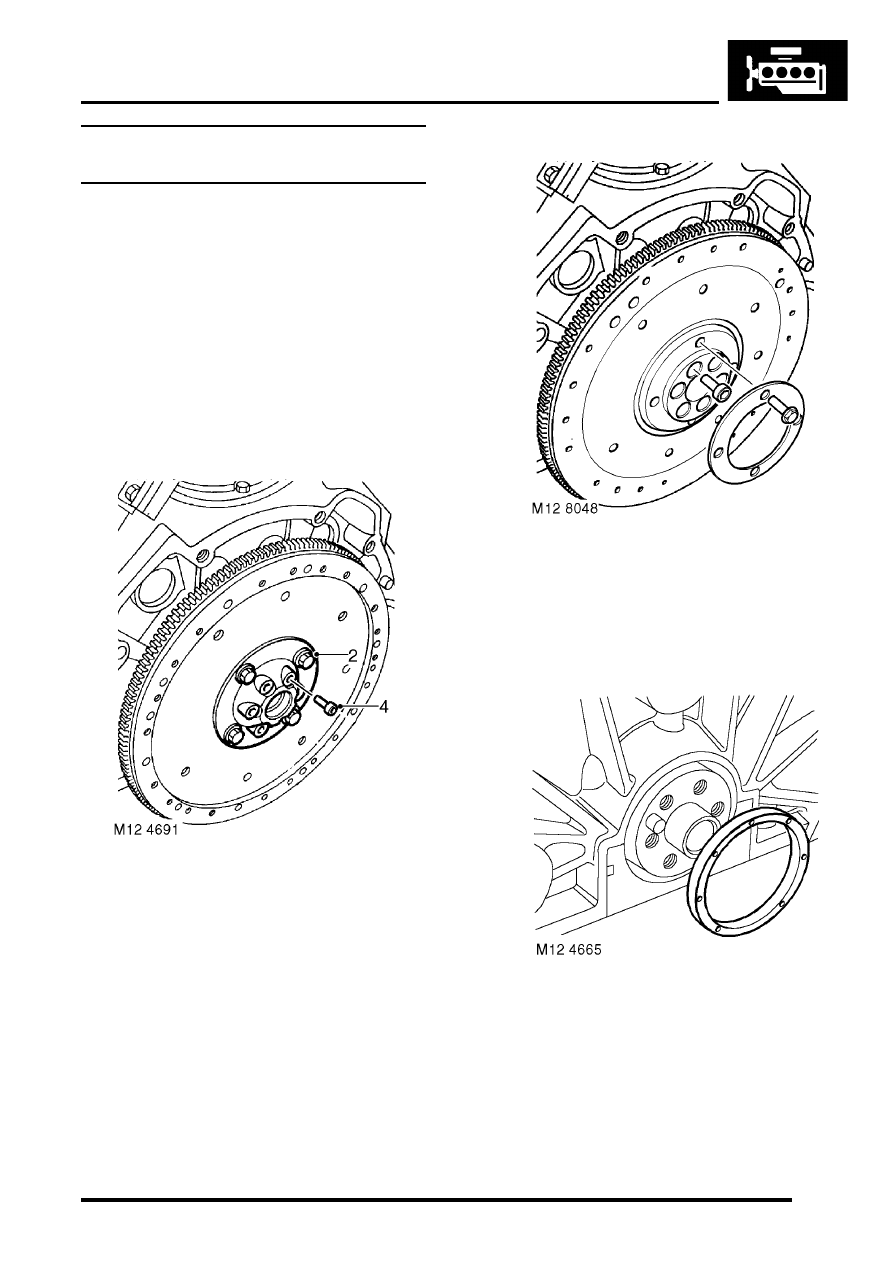
2. Early engines: Remove 4 bolts securing drive 

plate clamp ring and remove ring. 

3. Early engines: Remove drive plate from hub. 
4. Early engines: Remove 6 Allen bolts securing 

hub and starter ring gear, remove  hub, starter 
ring gear and collect spacer. 

Note: On early engines, balance weights are on 
engine side of drive plate, replacement drive 
plates will have balance weights on torque 
converter side of drive plate.

5. Later engines: Remove 4 bolts securing drive 

plate clamp ring and remove ring.

6. Later engines: Remove drive plate.
7. Later engines: Remove 6 Allen bolts securing 

starter ring gear to crankshaft, remove starter 
ring gear.

8. Carefully remove oil seal from cylinder  block to 

avoid damage to seal location or  running 
surface on crankshaft. 

ENGINE - V8

12-2-50 OVERHAUL

Reassembly

1. Ensure both seal location and running  surface 

on crankshaft are clean. Ensure that bolt holes 
in crankshaft are clean and dry.

2. Lubricate replacement oil seal with engine oil.
3. Lubricate seal guide LRT-12-095 with engine 

oil and position guide to crankshaft. 

4. Fit new seal squarely onto crankshaft and  

remove guide  LRT-12-095

5. Fit seal into location using tools LRT-12-091 

and LRT-99-003.   

6. All engines: Ensure bolt holes in crankshaft 

are clean and dry.

7. All engines: Clean all components.
8.  All engines: Check that drive plate is free from  

cracks and distortion. 

9. Early engines: Fit hub, starter ring gear and 

spacer to crankshaft,  tighten Allen bolts to 78 
Nm (58 lbf.ft). 

10. Early engines: Fit drive plate and clamp ring,  

tighten bolts to 45 Nm (35 lbf.ft). 

11.  Later engines: Fit starter ring gear, fit Allen 

bolts and tighten to 85 Nm (63 lbf.ft).

12. Later engines: Fit drive plate and clamp ring, 

fit bolts and tighten to 45 Nm (33 lbf.ft).

13. Fit CKP sensor. 


 + 

 ENGINE MANAGEMENT SYSTEM - 

V8, REPAIRS, Sensor - crankshaft position 
(CKP).

Seal - crankshaft - rear - manual models

$% 12.21.20.01 

Disassembly

1. Restrain flywheel. 
2. Working in sequence, loosen and remove 6 

bolts securing clutch cover to flywheel.

3. Remove clutch cover.
4. Remove clutch plate.
5. Remove CKP sensor.


 + 

 ENGINE MANAGEMENT SYSTEM - 

V8, REPAIRS, Sensor - crankshaft position 
(CKP).

6. Remove 6 bolts securing flywheel.
7. Remove flywheel.

ENGINE - V8

OVERHAUL 12-2-51

8. Carefully remove oil seal from cylinder block to 

avoid damage to seal location or running 
surface on crankshaft.

Reassembly

1. Ensure both seal location and running  surface 

on crankshaft are clean. Ensure that bolt holes 
are clean and dry.

2. Lubricate replacement oil seal with engine oil.
3. Lubricate seal guide LRT-12-095 with engine 

oil and position to  crankshaft. 

4. Fit new seal squarely onto crankshaft and 

remove guide LRT-12-095.

5. Fit seal into location using tools LRT-12-091 

and LRT-99-003

6. Clean mating faces of flywheel and crankshaft, 

dowel and dowel hole. 

7. Fit flywheel to crankshaft and, working in a 

diagonal sequence, tighten bolts to 78 Nm (58 
lbf.ft). 

8. Fit CKP sensor.


 + 

 ENGINE MANAGEMENT SYSTEM - 

V8, REPAIRS, Sensor - crankshaft position 
(CKP).

9. Clean clutch cover, drive plate and spigot bush 

in end of crankshaft.

10. Renew worn components as necessary.
11. If refitting existing drive plate, apply Molycote 

FB 108 to splines.

12. Fit LRT-12-001 alignment tool to spigot bearing 

in crankshaft.

13. Fit drive plate onto alignment tool, ensure side 

marked 'flywheel side' is against flywheel.

14. Fit clutch cover and locate on dowels.
15. Fit clutch cover bolts and tighten in diagonal 

sequence to 40 Nm (30 lbf.ft).

ENGINE - V8

12-2-52 OVERHAUL

Bearing - spigot - crankshaft 

$% 12.21.45.01 

Disassembly

1. Remove 6 bolts securing clutch cover. 
2. Remove clutch cover. 
3. Tap a thread in spigot bush to  accommodate a 

suitable impulse extractor. 

4. Fit extractor to bush. 

5. Remove bush from crankshaft. 

Reassembly

1. Clean bush register in rear of  crankshaft. 
2. Using a suitable drift, fit new bush to crankshaft 

so that it is flush with or up to a maximum of 1.6 
mm (0.06 in) below the end of the crankshaft. 

3. Ream spigot bush to 19.117 + 0.025 

 0.00 mm 

(0.75 + 0.001 

 0.00 in) . 

4. Remove all traces of swarf on completion.
5. Clean mating faces of flywheel and  crankshaft, 

dowel and dowel hole. 

6. Fit clutch cover to flywheel and  tighten bolts by 

diagonal slection to 40 Nm (30 lbf.ft). 


Content   ..  42  43  44  45   ..