Discovery 2. Manual - part 5
GENERAL INFORMATION
03-13
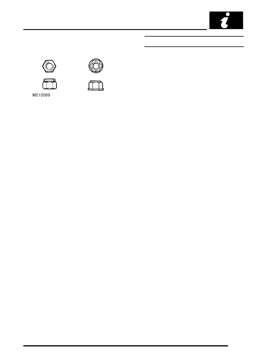
Self-locking nuts
Self-locking nuts, i.e. nylon insert or deferred thread
nuts can be re-used providing resistance can be felt
when the locking portion of the nut passes over the
thread of the bolt or stud.
Where self-locking nuts have been removed, it is
advisable to replace them with new ones of the same
type.
Flexible Pipes and Hoses
General
When removing and installing flexible hydraulic pipes
and hoses, ensure that the following practices are
observed to ensure component serviceability.
l
Before removing any brake or power steering
hose, clean end fittings and area surrounding
them as thoroughly as possible.
l
Obtain appropriate plugs or caps before
detaching hose end fittings, so that the ports can
be immediately covered to prevent the ingress
of dirt.
l
Clean hose externally and blow through with
airline. Examine carefully for cracks, separation
of plies, security of end fittings and external
damage. Reject any faulty hoses.
l
When refitting a hose, ensure that no
unnecessary bends are introduced, and that
hose is not twisted before or during tightening of
union nuts.
l
Fit a cap to seal a hydraulic union and a plug to
its socket after removal to prevent ingress of
dirt.
l
Absolute cleanliness must be observed with
hydraulic components at all times.
l
After any work on hydraulic systems, carefully
inspect for leaks underneath the vehicle while a
second operator applies maximum brake
pressure to the brakes (engine running) and
operates the steering.