Discovery electrical Manual - part 71
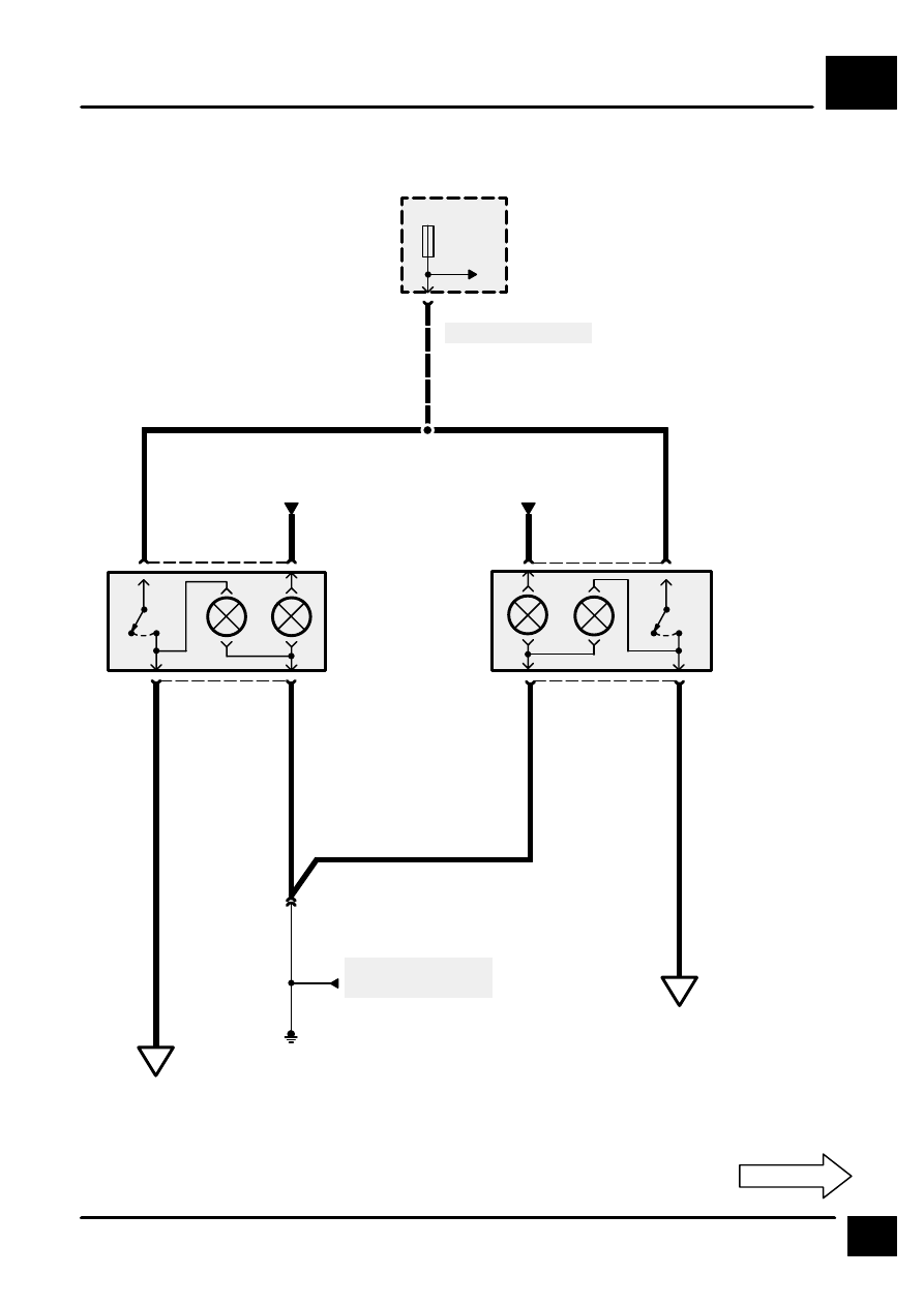
HEATED SEATS
M2
1
CIRCUIT DIAGRAM
S2124
15
F 15
10 A
0
2
C341
E303
See Fuse Details
P126
Fascia Fuse Box
22
C204
0
X143
Left Seat Heat
Switch
X164
Right Seat Heat
Switch
RN
1
5
C341
4
B
6
C3003
4
C342
5
1
C342
2
B
UK
US
See Ground Dis-
tribution
A
M2-2
B
M2-2
Interior Lamps
Interior Lamps
RN
LGP
[1]
[1]
LGP
HJ13