Discovery electrical Manual - part 59
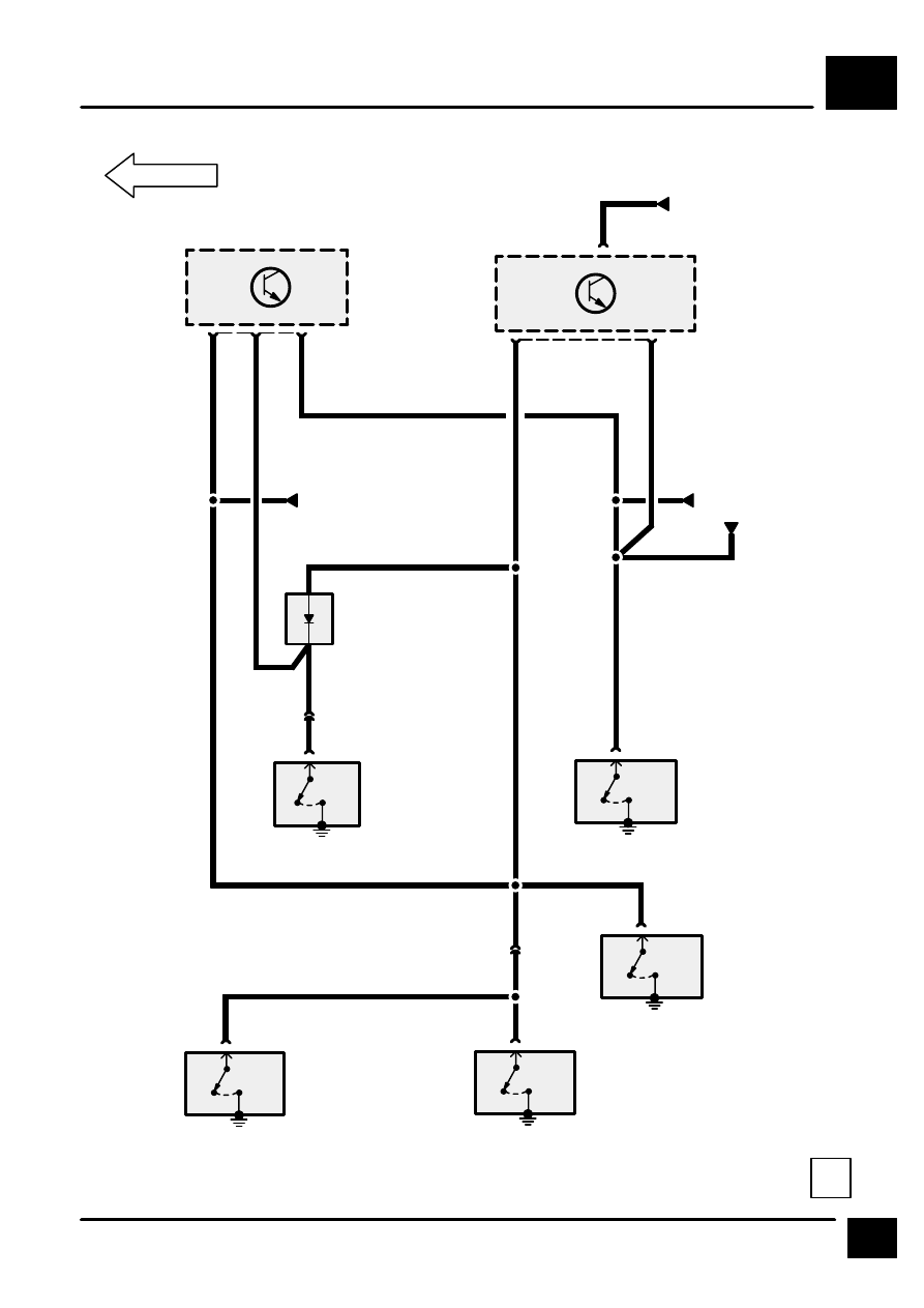
INTERIOR LAMPS
J1
13
REV: 06/97
18
PW
S261
0
[1]
1
C3008
X142
Left Rear Door
Switch
[1]
Open
0
[1]
1
C2087
X118
Right Front Door
Switch
[1]
Open
S309
0
[1]
1
C3009
X163
Right Rear Door
Switch
[1]
Open
1
C306
0
[1]
1
C2086
X150
Left Front Door
Switch
[1]
Open
Theft Alarm Sys-
tem (NAS)
PG
C205
S2106
0
[1]
1
C451
X265
Rear End Door
Switch
[1]
Open
Z148
Multi–Function
Unit (MFU)
2
C277
5
HJ4
Z163
Theft Alarm Unit
1
16
C225
PW
WP
PG
5
Z277
Tailgate Diode
S2013
HJ1
S2135
WP
1
C205
Interior Lamps
PU
S2136
Theft Alarm Sys-
tem (NAS)
NAS
From VIN 550523
& 717859