Discovery electrical Manual - part 35
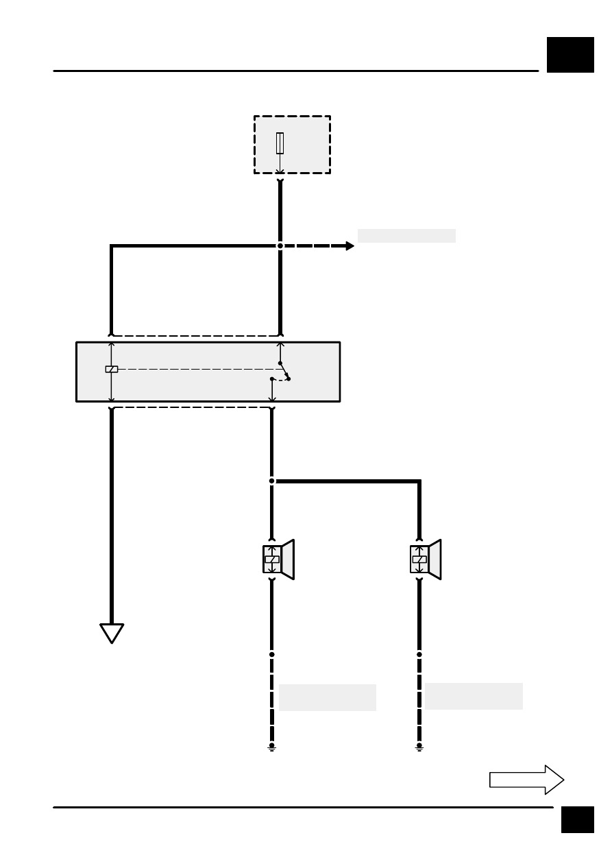
HORNS
E5
1
CIRCUIT DIAGRAM
S2089
30
F 4
30 A
E201
See Fuse Details
P125
Engine Compart-
ment Fuse Box
PN
C101
K189
Horn Relay
30
C283
85
PO
86
87
C283
PG
S2057
S288
See Ground Dis-
tribution
1
C169
2
C169
A
E5-2
K128
Left Horn
K134
Right Horn
1
C168
2
C168
30
85
86
87
B
B
1
HJ5
E200
S2016
HJ10
See Ground Dis-
tribution