Discovery electrical Manual - part 22


  Index      Land Rover     DISCOVERY ELECTRICAL TROUBLESHOOTING MANUAL 1997-1999 year


Search            


Content   ..  20  21  22  23   ..


Discovery electrical Manual - part 22


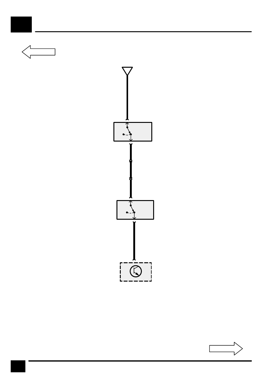
CRUISE CONTROL (EXCEPT NAS) (MANUAL TRANSMISSION)

B5

10

CIRCUIT DIAGRAM

Except NAS

PW

0

[1]

D

B5-9

0

[1]

1

C2035

1

C2005

9

C284

X200
Clutch Pedal
Position Switch

[1]

Clutch
Pedal De-
pressed

X112
Brake Switch
Vent Valve

[1]

Brake Pedal
Depressed

Z121
Cruise Control
ECU

2

C2035

2

C2005

6

C218

5

C218

P

PY

PG

P

Manual Trans-
mission

CRUISE CONTROL (MANUAL TRANSMISSION) (NAS)

B5

11

CIRCUIT DIAGRAM

NAS

WY

0

[1]

B5-5

0

[1]

1

C2035

1

C2005

9

C284

X200
Clutch Pedal
Position Switch

[1]

Clutch
Pedal De-
pressed

X112
Brake Switch
Vent Valve

[1]

Brake Pedal
Depressed

Z121
Cruise Control
ECU

2

C2035

2

C2005

6

C218

5

C218

P

PY

PG

P

4

C218

3

C218

WS

D

Z186
Cruise Control
Diode

Manual Trans-
mission

IGNITION AND SHIFT INTERLOCK

C1

CIRCUIT OPERATION

1

REV: 11/97

CIRCUIT OPERATION

Selector Interlock

When the gear selector is in the park position, the
solenoid inside the Transmission Range Selector
Switch (Z110) is de–energised and prevents the
selector from being moved into another gear. To free
the selector, the Ignition Switch (X134) must be in
position II and the brake pedal must be depressed.
When this occurs, voltage from Fuse F1 is applied to
the Transmission Range Selector through the closed
Stop Lamp Switch (X168). The solenoid inside the
Transmission Range Selector Switch is grounded at
E200 through the selector switch, the KS wire and
the B wire. The solenoid now energises, freeing the
selector.

Ignition Key Interlock

On vehicles equipped with the interlock safety
feature, the vehicle must be in park and the transfer
case in high or low gear before the key can be
removed from the ignition. If the gear selector or
transfer gear is out of gear, the key must be cycled
before removal.

If the vehicle is not in park, voltage from Fuse F12 is
applied to the Key Barrel Switch (X230) through the
closed contacts of the Transmission Range Selector
Switch (Z110). When the ignition switch is placed in
the 0 position, the Key Barrel Switch (X230) closes
to energise the solenoid and prevent key removal.

If the key is in the ignition and the transfer box is in
the neutral position, Interlock Relay 1 (K153) is
de–energised since the relay coil is not grounded by
the Transfer Box Position Switch (X175). When the
relay is de–energised, voltage is applied to the Key
Barrel Switch (X230) through the relay’s switch
contacts and the Key–In Switch (X229) causing the
solenoid to energise and prevent key removal.

If the Transfer Box is in the “H” or “L” position, the
Interlock Relay 1 (K153) is energised, since the relay
coil is grounded by the Transfer Box Position Switch
(X175). When the relay is energised, voltage to the
Key Barrel Switch (X230) is interrupted. If the vehicle
is in Park the Transmission Range Selector Switch
(Z110) contacts are open. When the switch contacts
are open, voltage to the Key Barrel Switch (X230) is
also interrupted. The Ignition Key Lock Solenoid
(K191) is then disabled, allowing removal of the key.

Transfer Box Interlock (NAS vehicles with 
automatic transmission only)

The Transfer Box Interlock safety feature is designed
to prevent the transfer case shifter from being shifted
out of “H” or “L” unless the vehicle’s gear selector is
in the neutral position.

When the gear selector is placed in the neutral
position, voltage is applied to the Interlock Relay 2’s
coil through the Transmission Range Selector Switch
(Z110). The relay’s coil is grounded through the
Park/Neutral Position Switch (X167).

Interlock Relay 2 now energises and applies voltage
from Fuse F13 to the Transfer Box Solenoid (K161).
When the Transfer Box Solenoid (K161) is energised
the transfer box shifter can be operated. 

IGNITION AND SHIFT INTERLOCK

C1

2

CIRCUIT DIAGRAM

10

P126
Fascia Fuse Box

C204

C227

C227

Without ABS

With ABS

S2011

X168
Stop Lamp
Switch

[1]

Brake Pedal
Depressed

[2]

Brake Pedal
Further De-
pressed

1

X168
Stop Lamp
Switch

[1]

Brake Pedal
Depressed

[2]

Brake Pedal
Further De-
pressed

GO

2

15

F 1

15A

[1]

[2]

0

S2042

GP

[1]

C2063

0

GO

1

C2004

C2063

1

C2003

GP

Z206
Stop Lamp
Switch Sup-
pressor

With ABS

Stop Lamps

Without ABS

GO

HJ1

2

GP

HJ3

See Fuse Details

[2]

R

R

1

A

C1-3


Content   ..  20  21  22  23   ..