Discovery electrical Manual - part 4
INTRODUCTION
i
10
[0]
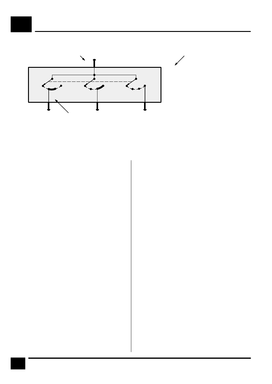
X134
Ignition
Switch
[0] 0, off
[1] I, radio
[2] II, ignition
[3] III, start
[1]
[2]
[3] [0]
[1]
[2]
[3] [0]
[1]
[2]
[3]
R
15
50
30
5
3
4
2
Terminal number
Component designation
R" receives battery voltage
in positions I, II
Terminal
number
Designation
50
Battery voltage: Ignition
Switch in position III
30
Battery voltage: supplied
constantly
15
Battery voltage: Ignition
Switch in position II or III
R
Battery voltage: Ignition
Switch in positions I, II
31
Terminal
number
Designation
X
Switched battery voltage
through the ignition load reĆ
lay or accessory relay; igniĆ
tion switch is in position I or
II.
49
Flasher unit input
49aFla
sher unit output
56aHigh bea
m
56b
Low beam
85
End of relay coil
86
Start of relay coil
87
Relay contact
87a
Relay contact
Ground
50
Start
56
Headlamp
56d
Headlamp flash
58
Side lamps