Discovery (1995+): Body Repair Manual - part 2


  Index      Land Rover     Discovery Body Repair Manual - 1995 year


Search            


Content   ..  1  2  3   ..


Discovery (1995+): Body Repair Manual - part 2


01

INTRODUCTION

8

INFORMATION

Two wheel dynamometers

IMPORTANT: Use a four wheel dynamometer for
brake testing if possible.

NOTE: ABS will not function on a two
wheel dynamometer. The ABS light will
illuminate during testing. Normal braking

will be available.

If brake testing on a single rig is necessary it must be
carried out with propeller shaft to the rear axle
removed, AND neutral selected in BOTH main and
transfer boxes.

If checking engine performance, the transfer box must
be in high range and drive shaft to stationary axle
removed.

TOWING

CAUTION: The vehicle has permanent
four-wheel drive. The following towing
instructions must be adhered to:

Towing the vehicle on all four wheels with driver
operating steering and brakes.

1. Turn ignition key turn to position ’1’ to release

steering lock.

2. Select neutral in main gearbox and transfer

gearbox.

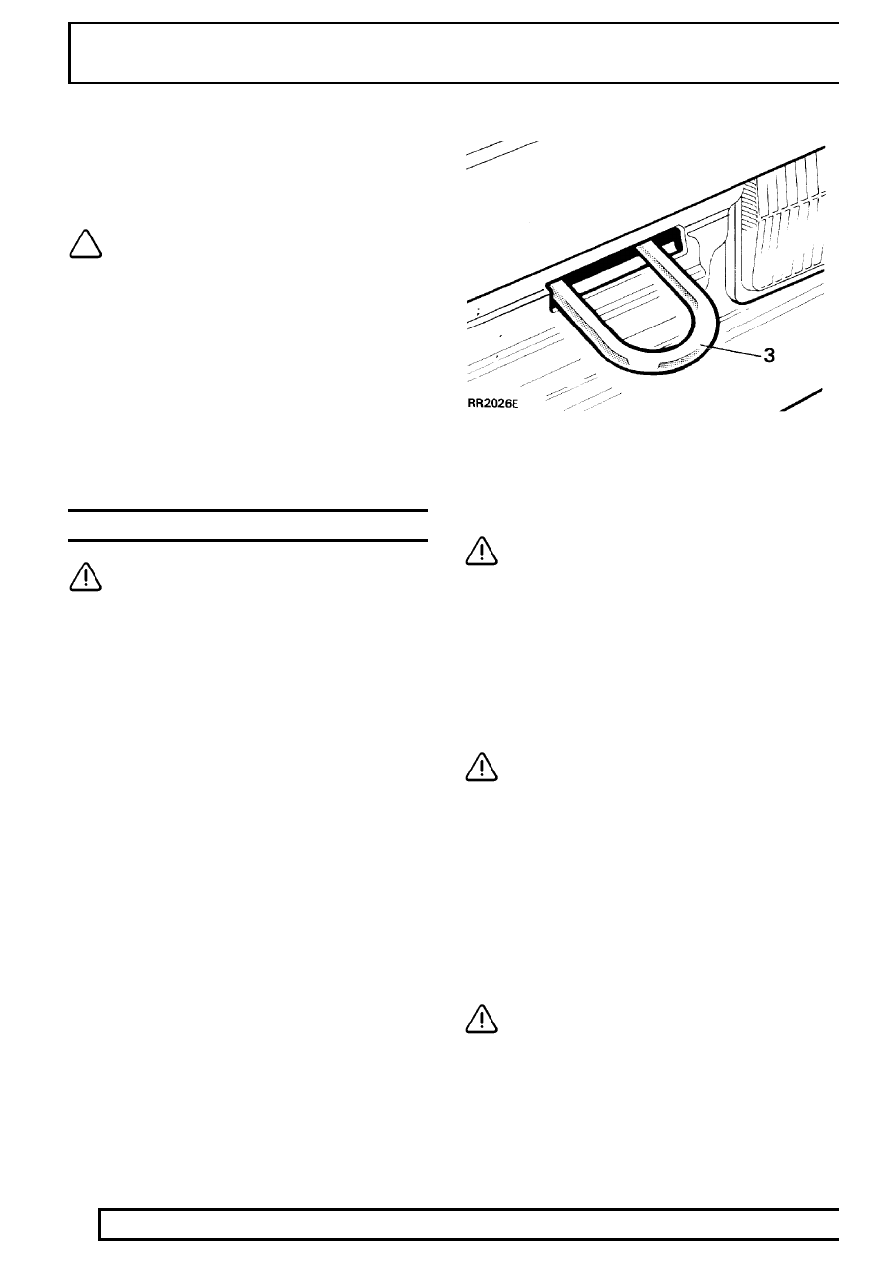
3. Secure tow rope, chain or cable to towing eye.
4. Release the parking brake.

CAUTION: The brake servo and power
assisted steering system will not be
functional without the engine running.

Greater pedal pressure will be required to apply
the brakes, the steering system will require
greater effort to turn the front road wheels.
The vehicle tow connection should be used only
in normal road conditions, ’snatch’ recovery
should be avoided.

Suspended tow by breakdown vehicle

CAUTION: To prevent vehicle damage,
front or rear propeller shaft MUST BE
removed, dependent upon which axle is

being trailed.

1. Mark propeller shaft drive flanges at transfer

gearbox and axles with identification lines to
enable the propeller shaft to be refitted in its
original position.

2. Remove the propeller shaft fixings, remove the

shaft from the vehicle.

3. If the front axle is to be trailed turn ignition key to

position ’1’ to release steering lock.

CAUTION: The steering wheel and/or
linkage must be secured in a straight
ahead position. DO NOT use the steering

lock mechanism for this purpose.

INTRODUCTION

9

INFORMATION

TRANSPORTING THE VEHICLE BY TRAILER

Lashing eyes are provided on front and rear of the
chassis side members, to facilitate the securing of the
vehicle to a trailer or other means of transportation.

CAUTION: Underbody components must
not be used as lashing points.

Install vehicle on trailer and apply park brake. Select
neutral in main gearbox. Selecting ’N’ will prevent
damage to parking pawl of the automatic gearbox.

FRONT OF CHASSIS

REAR OF CHASSIS

JUMP STARTING

WARNING: Hydrogen and oxygen gases
are produced during normal battery
operation. This gas mixture can explode if

flames, sparks or lighted tobacco are brought
near battery. When charging or using a battery in
an enclosed space, always provide ventilation and
shield your eyes.

Keep out of reach of children. Batteries contain
sulphuric acid. Avoid contact with skin, eyes, or
clothing. Also, shield eyes when working near
battery to protect against possible splashing of
acid solution. In case of acid contact with skin,
eyes, or clothing, flush immediately with water for
a minimum of fifteen minutes. If acid is swallowed,
drink large quantities of milk or water, followed by
milk of magnesia, a beaten egg, or vegetable oil.
SEEK MEDICAL AID IMMEDIATELY.

To Jump Start - Negative Ground Battery

WARNING: To avoid any possibility of
injury use particular care when connecting
a booster battery to a discharged battery.

1. Position vehicles so that jump leads will reach,

ensuring that vehicles DO NOT TOUCH,
alternatively a fully charged slave battery may be
positioned on floor adjacent to vehicle.

2. Ensuring that ignition and all electrical

accessories are switched off, that parking brake
is applied and neutral is selected on a manual
gearbox, with an automatic gearbox select
neutral (N) or park (P) and then connect the
jump leads as follows;

A. Connect one end of first jumper cable to positive

(+) terminal of booster battery.

B. Connect other end of first jumper cable to

positive (+) terminal of discharged battery.

C. Connect one end of second jumper cable to

negative terminal of booster battery.

01

INTRODUCTION

10

INFORMATION

D. Connect other end of second jumper cable to a

good earth point on the engine, NOT TO
NEGATIVE TERMINAL OF DISCHARGED
BATTERY. 
Keep jumper lead away from moving
parts, pulleys, drive belts and fan blade
assembly.

WARNING: Making final cable connection
could cause an electrical arc which if
made near battery could cause an

explosion.

3. If booster battery is installed in another vehicle,

start engine and allow to idle.

4. Start engine of vehicle with discharged battery,

following starting procedure in Owners’ Manual.

CAUTION: If vehicle fails to start within a
maximum time of 12 seconds, switch
ignition off and investigate cause. Failing

to follow this instruction could result in
irrepairable damage to catalysts.

5. Remove negative (-) jumper cable from the

engine and then terminal of booster battery.

6. Remove positive (+) jumper cable from positive

terminals of booster battery and discharged
battery.

VEHICLE IDENTIFICATION NUMBER (VIN)

The Vehicle Identification Number and the
recommended maximum vehicle weights are stamped
on a plate located under the bonnet [hood] riveted to
the front of the engine compartment.

Vehicle Identification Number Plate (UK, Australia,
R.O.W., Europe)

A.

Build date (Australia). Type approval

B.

VIN (17 digits)

C.

Maximum permitted laden weight for vehicle

D.

Maximum vehicle and trailer weight

E.

Maximum road weight-front axle

F.

Maximum road weight-rear axle

The number is also stamped on the right side of the
chassis forward of the spring mounting turret.

INTRODUCTION

11

INFORMATION

Vehicle Identification Number Plate (Saudi Arabia)

A.

Year of manufacture

B.

Month of manufacture

C.

Maximum vehicle weight

D.

Maximum road weight-front axle

E.

Maximum road weight-rear axle

F.

VIN (17 digits)

The vehicle identification number identifies the
manufacturer, model range, wheel base, body type,
engine, steering, transmission, model year and place
of manufacture. The following example shows the
coding process.

SAL World manufacturer identifier
LH

Range Rover or

LJ

Discovery

G

Class 100 inch

B

2 door

F

300 Tdi or

V

V8i Petrol

8

5 speed LHD or

7

5 speed RHD

M

1995 MY

A

Solihull site

European vehicle identification number (VIN)

Stamped on the right hand side chassis forward of
rear wheel.

Federal (USA) vehicle identification number

Stamped on a plate rivetted to the upper left hand ’A’ -
post, visible through the front screen of the vehicle.


Content   ..  1  2  3   ..