Land Rover Discovery. Manual - part 226


  Index      Land Rover     Land Rover Discovery - service 1995-1996 year


Search            


Content   ..  224  225  226  227   ..


Land Rover Discovery. Manual - part 226


ENGINE

8

OVERHAUL

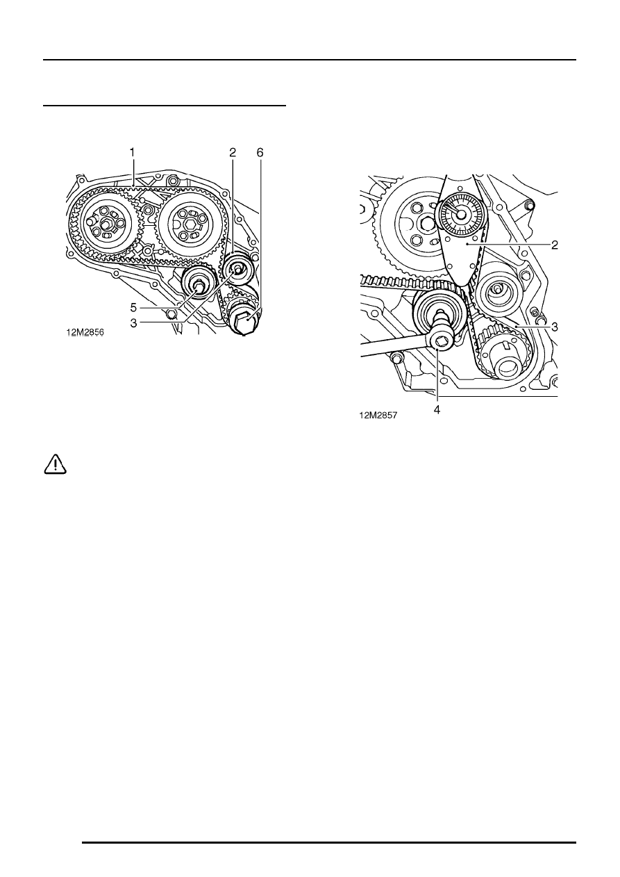
Timing belt - refit and adjust tension

Refit

1. Using the fingers only, fit a new timing belt to

timing gears keeping slack portion of belt on
idler pulley side of belt. If necessary, rotate fuel
injection pump gear anti-clockwise to align
gear teeth with those of timing belt.

CAUTION: If original timing belt is to be
refitted, ensure direction of rotation mark
is facing correct way.

2. Fit idler pulley.
3. Fit idler pulley nut and tighten to 45 Nm.
4. Ensure that timing belt is correctly located on

timing gears.

5. Check that tensioner pulley bolt is finger tight.
6. Temporarily fit crankshaft pulley bolt to

crankshaft.

Adjust tension

1. Ensure tools LRT-12-044 and LRT-12-045

are still fitted.

2. Position a dial type torque wrench and suitable

extension to hole in tensioner bracket keeping
the torque wrench positioned vertically.

3. Tension timing belt to :

Used belt - 12 Nm
New belt - 15 Nm

4. Keeping timing belt at the correct tension,

tighten tensioner bolt to 45 Nm.

ENGINE

OVERHAUL

9

5. Check that timing pin LRT-12-045 moves

freely in and out of injection pump hub, if pin
does not move freely, slacken 3 bolts, move
gear slightly and re-check.

6. When timing pin moves freely, tighten 3 bolts

to 25 Nm.

7. Remove timing pin LRT-12-045 and

flywheel/drive plate locking tool LRT-12-044.

8. Rotate crankshaft twice in a clockwise direction

using crankshaft pulley bolt until flywheel/drive
plate locking tool LRT-12-044 can be refitted.

9. Slacken timing belt tensioner securing bolt and

re-tension timing belt.

10. Tighten tensioner bolt to 45 Nm.
11. Fit timing pin LRT-12-045 into fuel injection

pump gear hub plate and pump hub. If timing
pin cannot be inserted, slacken injection pump
gear bolts, rotate pump shaft using shaft nut
until pin slides easily into pump hub, Tighten
bolts to 25 Nm.

12. Tighten camshaft gear bolt to 80 Nm.
13. Remove timing pin and flywheel/drive plate

locking tools.

14. Fit plug to flywheel housing, tighten to 12 Nm.
15. Remove crankshaft pulley bolt.

16. Support timing belt front cover on suitable

blocks of wood.

17. Smear a new crankshaft oil seal with engine

oil.

18. Using tool LRT-12-077, fit oil seal from inside

face of front cover.

19. Fit a dry, new gasket to timing belt rear cover.
20. Position timing belt front cover to rear cover.
21. Fit bolts of the correct length in positions

shown.

ENGINE

10

OVERHAUL

22. Tighten bolts in sequence shown to 25 Nm.
23. Lightly oil crankshaft spigot, fit Woodruff key

and crankshaft pulley.

24. Position tool LRT-12-080 to crankshaft pulley,

retain tool using 4 bolts.

25. Fit crankshaft pulley flange head bolt.
26. Restrain crankshaft and tighten bolt to 80

Nm,then further 90.

°

27. Remove tool LRT-12-080.

ENGINE

OVERHAUL

11

ROCKER SHAFT

Remove

1. Disconnect breather hoses from crankcase

breather cyclone unit.

2. Remove bolt securing cyclone unit to rocker

cover.

3. Remove cyclone unit, remove and discard ’O’

ring.

4. Disconnect breather hoses from cylinder block

and rocker cover.

5. Remove 3 flange nuts securing rocker cover,

recover sealing washers.

6. Remove rocker cover, remove and discard

gasket.

7. Slacken locknut on each tappet adjusting

screw, slacken adjusting screws until they are
clear of push rods.

8. Working from the centre outwards,

progressively slacken then remove 3 nuts and
2 bolts securing rocker shaft pedestals to
cylinder head.

CAUTION: Insert a slave bolt into
pedestals 1 and 5 to prevent components
sliding off shaft.

9. Remove rocker shaft assembly.


Content   ..  224  225  226  227   ..