Land Rover Discovery. Manual - part 212


  Index      Land Rover     Land Rover Discovery - service 1995-1996 year


Search            


Content   ..  210  211  212  213   ..


Land Rover Discovery. Manual - part 212


ELECTRICAL

27

REPAIR

WINDOW LIFT MOTOR - FRONT

Service repair no - 86.25.04

Remove

1. Ensure that the window glass is in its fully closed

position and secure it with adhesive tape.

2. Disconnect battery negative lead.
3. Remove the door pull, trim panel, and plastic

vapour barrier.

See CHASSIS AND BODY,

Repair, Front Door Trim Panel

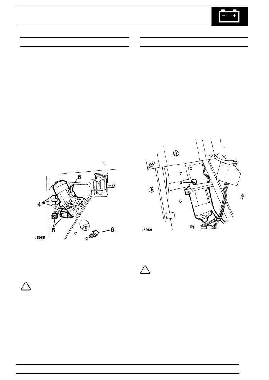
4. Release the window lift motor wiring harness

from the three retaining clips to allow the
harness to be pulled out of the opening at the
front of the inner door panel.

5. Disconnect the window lift motor harness

multi-plug from the main door harness.

6. Support the motor, remove the three securing

bolts and withdraw the motor through the top
front opening of the door panel.

Refit

7. Reverse removal procedure.

NOTE: Ensure drive gear is engaged and
correctly aligned with window lift linkage
before fitting securing bolts.

WINDOW LIFT MOTOR - REAR

Service repair no - 86.25.09

Remove

1. Ensure that the side door glass is in the fully

closed position and secure with adhesive tape.

2. Disconnect battery negative lead.
3. Remove the door pull, trim panel and plastic

vapour barrier.

See CHASSIS AND BODY,

Repair, Rear Side Door Trim - Panel

4. Disconnect the lift motor harness multi-plug from

the door harness.

5. Support the motor and remove the three

securing screws.

6. Withdraw the motor through the lower opening in

the inner door panel.

Refit

7. Reverse removal procedure.

NOTE: Ensure drive gear is engaged and
correctly aligned with window lift linkage,
before fitting securing bolts.

86

ELECTRICAL

28

REPAIR

INSTRUMENT PANEL FINISHER

Service repair no - 88.20.03

Remove

1. Position steering wheel for access.

2. Remove 2 screws securing panel.
3. Lift panel clear, disconnect multiplug

connections.

Refit

4. Reverse removal procedure.

ELECTRICAL

29

REPAIR

INSTRUMENT BINNACLE

Service repair no - 88.20.13

Remove

1. Remove instrument panel finisher.

See

Instrument panel finisher

2. Remove 4 screws securing binnacle to fascia.
3. Carefully ease 2 lower panel finisher brackets

downwards.

4. Withdraw binnacle to gain access to multiplugs.
5. Noting their fitted positions, disconnect

multiplugs.

6. Remove binnacle.

Refit

7. Reverse removal procedure.

86

ELECTRICAL

30

REPAIR

INSTRUMENT ILLUMINATION AND WARNING
LIGHT BULBS

Service repair no - 86.45.48 - Instrument
Service repair no - 86.45.61 - Warning light

Remove

1. Remove binnacle.

See Instrument binnacle

2. Identify bulb to be replaced.

NOTE: If faulty bulb is not accessible,
remove screws securing circuit board and
carefully ease circuit board aside.

3. Rotate bulb holder anti-clockwise, withdraw bulb

holder and remove bulb.

Refit

4. Fit new bulb to holder.

CAUTION: Ensure bulb of correct wattage
and type is fitted.

5. Reverse removal procedure.


Content   ..  210  211  212  213   ..